
Page 111 - The Effect of Hydrogen and Hydrides - ebook first test
P. 111
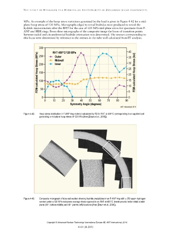
Figure 4-42: Hoop stress distribution in F-ANP ring material calculated by FE for RHT at 400C corresponding to an applied load
generating a mid-plane hoop stress of 120 MPa (from [Daum et al., 2006]).
Figure 4-43: Composite micrograph of tube wall section showing hydride precipitates in an F-ANP ring with 250 wppm hydrogen
content under a 120 MPa mid-plane average stress exposed to an RHT at 400C. Insets provide better detail at mid-
plane (90; bottom middle) and 40 (centre, left) locations (from [Daum et al., 2006]).
Copyright © Advanced Nuclear Technology International Europe AB, ANT International, 2019.