
Page 130 - Basic Course
P. 130
KNX BASIC COURSE
PL‐System Powerline Line 3
coupler 3
Device Device
1 255
nd
2 floor
KNX TP Main line PL‐System Device Device
Powerline Line 2
coupler 2
255
1
st
1 floor
PL‐System Powerline Line 1
coupler 1
Device Device
1 255
Ground floor
3 x 230 V
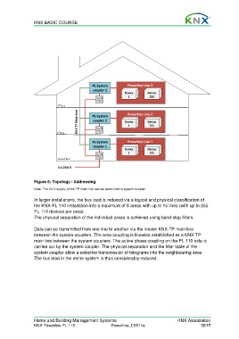
Figure 8: Topology / Addressing
Note: The 24 V supply of the TP main line can be taken from a system coupler.
In larger installations, the bus load is reduced via a logical and physical classification of
the KNX-PL 110 installation into a maximum of 8 areas with up to 15 lines (with up to 255
PL 110 devices per area).
The physical separation of the individual areas is achieved using band-stop filters.
Data can be transmitted from one line to another via the known KNX-TP main line
between the system couplers. The area coupling is likewise established as a KNX-TP
main line between the system couplers. The active phase coupling on the PL 110 side is
carried out by the system coupler. The physical separation and the filter table of the
system coupler allow a selective transmission of telegrams into the neighbouring area.
The bus load in the entire system is thus considerably reduced.
Home and Building Management Systems KNX Association
KNX Powerline PL 110 Powerline_E0814a 12/17