
Page 42 - Basic Course
P. 42
KNX BASIC COURSE
1 Topology - Overall view
Backbone line
BC BC
x.0.0 DVC 1 DVC 49 15.0.0
Main line
LC
x.x.0 LC
DVC 1
Maximum x.x.1 DVC 1
64 devices
DVC 63 Secondary line (1st line segment)
x.x.63
LR LR LR
x.x.64 x.x.128 x.x.192 DVC 63
3 x DVC 65 DVC 129 DVC 193
maximum x.x.65 x.x.129 x.x.193
64 devices
DVC 127 DVC 191 DVC 255
x.x.127 x.x.191 x.x.255
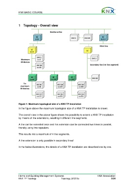
Figure 1: Maximum topological size of a KNX TP installation
In the figure above the maximum topological size of a KNX TP installation is shown.
The overall view in the above figure shows the possibility to extend a KNX TP installation
by means of line extensions, resulting in different line segments.
A line can be extended once and this extension can be connected two times in parallel,
thereby using line repeaters.
This results into a maximum of 4 line segments.
A line extension is only possible in secondary lines!
In the below illustrations, the details of a KNX TP installation are described one by one.
Home and Building Management Systems KNX Association
KNX TP Topology Topology_E1213a 3/24