Page 50 - Basic Course
P. 50

KNX BASIC COURSE

                  9  Connecting several lines


                                          Switch
                             PS/Ch
                                         Actuator
                                                                                               Line 0


                              SV/Dr
                                                Switch
                             PS/Ch       LC
                                               Actuator
                                         2  1
                                                                                               Line 1


                              SV/Dr
                                                Switch
                             PS/Ch       LC
                                               Actuator
                                         2  1
                                                                                               Line 2

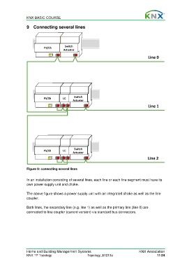
                  Figure 9: connecting several lines

                  In an installation consisting of several lines, each line or each line segment must have its
                  own power supply unit and choke.

                  The above figure shows a power supply unit with an integrated choke as well as the line
                  coupler.

                  Both lines, the secondary line (e.g. line 1) as well as the primary line (line 0) are
                  connected to line coupler (current version) via standard bus connectors.


                  Home and Building Management Systems                                    KNX Association
                  KNX TP Topology                        Topology_E1213a                             11/24
   45   46   47   48   49   50   51   52   53   54   55