
Page 79 - Basic Course
P. 79
KNX BASIC COURSE
2 Internal structure of a Bus Coupling Unit
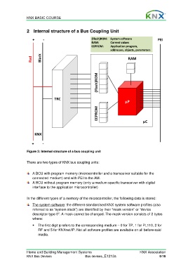
+ ‐ (Flash)ROM: System software PEI
RAM: Current values
EEPROM: Application program,
addresses, objects, parameters
Red Black RAM
(Flash)ROM
TRC
µP
EEPROM
µC
KNX
+ ‐
Figure 2: Internal structure of a bus coupling unit
There are two types of KNX bus coupling units:
A BCU with program memory (microcontroller and a transceiver suitable for the
connected medium) and with PEI to the AM.
A BCU without program memory (only a medium specific transceiver with digital
interface to the application microcontroller)
In the different types of a memory of the microcontroller, the following data is stored:
The system software: the different standardised KNX system software profiles (also
referred to as “system stack”) are identified by their “mask version” or “device
descriptor type 0”. A mask cannot be changed. The mask version consists of 2 bytes
where:
The first digit y refers to the corresponding medium – 0 for TP, 1 for PL110, 2 for
RF and 5 for KNXnet/IP. Not all software profiles are available on all before-said
media.
Home and Building Management Systems KNX Association
KNX Bus Devices Bus devices_E1213a 5/16