
Page 53 - Ag Resource Binder (English)
P. 53
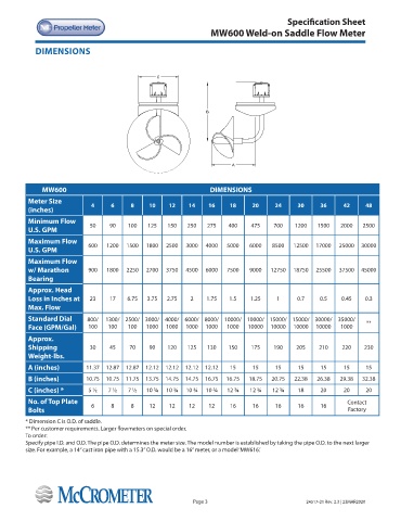
Specification Sheet
                                                                 MW600 Weld-on Saddle Flow Meter


            DIMENSIONS


                                                 C


                                                                B


                                                                        A


              MW600                                              DIMENSIONS
          Meter Size         4     6     8     10    12    14    16    18     20     24     30     36     42     48
          (inches)
          Minimum Flow      50    90    100   125   150   250   275    400    475    700   1200   1500   2000   2500
          U.S. GPM
          Maximum Flow      600   1200  1500  1800  2500  3000  4000  5000   6000   8500   12500  17000  25000  30000
          U.S. GPM
          Maximum Flow
          w/ Marathon       900   1800  2250  2700  3750  4500  6000  7500   9000   12750  18750  25500  37500  45000
          Bearing
          Approx. Head
          Loss in Inches at   23  17    6.75  3.75  2.75   2    1.75   1.5   1.25    1      0.7    0.5   0.45   0.3
          Max. Flow
          Standard Dial     800/  1300/ 2500/  3000/  4000/  6000/  8000/  10000/  10000/  15000/  15000/  30000/  35000/   **
          Face (GPM/Gal)    100   100   100   1000  1000  1000  1000  1000   10000  10000  10000  10000  1000

          Approx.
          Shipping          30    45     70    90   120   125   130    150    175    190   205    210    220    230
          Weight-lbs.
          A (inches)       11.37  12.87  12.87  12.12  12.12  12.12  12.12  15  15   15     15     15     15     15
          B (inches)       10.75  10.75  11.75  13.75  14.75  14.75  16.75  16.75  18.75  20.75  22.38  26.38  29.38  32.38
          C (inches) *      5 ½   7 ½   7 ½   10 ¾   10 ¾   10 ¾  10 ¾  12 ¾  12 ¾  12 ¾    18     20     20     20
          No. of Top Plate   6     8     8     12    12    12    12    16     16     16     16     16      Contact
          Bolts                                                                                            Factory
         * Dimension C is O.D. of saddle.
         ** Per customer requirements. Larger flowmeters on special order.
         To order:
         Specify pipe I.D. and O.D. The pipe O.D. determines the meter size. The model number is established by taking the pipe O.D. to the next larger
         size. For example, a 14” cast iron pipe with a 15.3” O.D. would be a 16” meter, or a model ‘MW616.’


                                                            Page 3                            24517-21 Rev. 2.3 | 23MAR2020