
Page 609 - YG 2019
P. 609
i-Xmill ZRT SERIES i-Xmill
END MILLS ZRS SERIES END MILLS RECOMMENDED CUTTING CONDITIONS
i-Xmill CORNER RADIUS HOLDERS - STEEL ASSEMBLY OF
▶ Premium alloy steel with excellent strength.
▶ Precise shank, Tolerance (h6). SIZE CLAMPING
▶ Nickel plated, to prevent corrosion and improve lubricity. TORQUE
ØD [ in•lbs ]
Ø5/16 (Ø8) 9.0
Ø3/8 (Ø10) 13.5
D3
Ø1/2 (Ø12~Ø13) 22.5
D2 D1 Ø5/8 (Ø16~Ø17) 31.5
Ø3/4 (Ø20~Ø21) 44.5
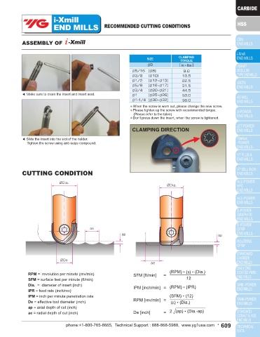
L1 ◀ Make sure to clean the insert and insert seat.
L3 Ø1 (Ø25~Ø26) 53.0
Ø1-1/4 (Ø30~Ø32) 58.0
L2
✽When the screw is worn out, please change the new screw.
✽Please tighten up the screw with recommended torque.
(Please refer to the table)
✽Don't press down the insert, when the screw is tightened.
Taper neck Type Unit : mm
Mill Shank Length Length Overall Neck Interference CLAMPING DIRECTION
EDP No. Diameter Diameter of Cut Below Shank Length Diameter Angle Length Wrench Screw
No.
Type
No.
D1 D2 L1 L3 L2 D3 θ˚ ◀ Slide the insert into the slot of the holder.
ZRT8011 22 100 9˚ Regular Tighten the screw using anti-seize compound.
ZRT8021 8.0 12 10 50 130 6.7 2˚ 43' Long TWF07 TX0807
ZRT1001 25 100 4˚ 45' Regular
ZRT1002 10.0 12 13 50 150 8.6 1˚ 32' Long TWF08 TX1008
12.0
ZRT1202 16 15 60 160 10.2 2˚ 32' Long TWF10 TX1210
13.0
CUTTING CONDITION
Straight neck Type Unit : mm
Mill Shank Length Length Overall Neck
EDP No. Diameter Diameter of Cut Below Shank Length Diameter Length Wrench Screw
No.
Type
No.
D1 D2 L1 L3 L2 D3
12.0
ZRS1120 13.0 12 13 30 110 11 Regular TWF10 TX1210
ZRS1160 16.0 50 130 Regular
ZRS2160 17.0 16 15 65 165 15 Intermediate TWF15 TX1615
ZRS1200 20.0 60 140 Regular (RPM)•(π)•(Dia.)
ZRS2200 21.0 20 18 80 180 19 Intermediate TWB20 TX2020 RPM = revolution per minute (rev/min) SFM [ft/min] =
ZRS1250 25.0 70 150 Regular SFM = surface feet per minute (ft/min) 12
ZRS2250 26.0 25 23 90 200 24 Intermediate TWB25 TX2525 Dia. = diameter of insert (inch)
ZRS1300 80 160 Regular IPR = feed rate (inch/rev) IPM [inch/min] = (RPM)•(IPR)
ZRS2300 30.0 32 27 100 220 29 Intermediate TWB30 TX3030 IPM = inch per minute penetration rate (SFM)•(12)
ZRS1320 80 160 Regular RPM [rev/min] =
ZRS2320 32.0 32 28 100 220 31 Intermediate TWB30 TX3030 De = effective tool diameter (inch) (π)•(Dia.)
● Need to use T Handle : TWH600 (See page 52) ap = axial depth of cut (inch)
ae = radial depth of cut (inch) De [inch] = 2 (ap)•(Dia.-ap)
608 • phone:+1-800-765-8665, Technical Support : 888-868-5988, www.yg1usa.com phone:+1-800-765-8665, Technical Support : 888-868-5988, www.yg1usa.com • 609