
Page 92 - CarrLaneCatalog_2019ed-c.pdf
P. 92
LIFTING EYES
STEEL: FORGED CARBON STEEL, QUENCHED AND DRAWN, PLAIN FINISH
STAINLESS STEEL: FORGED 316 STAINLESS STEEL, PASSIVATED AND ELECTROPOLISHED
Now also available in 316 stainless steel and metric sizes!
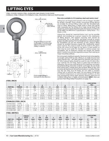
Lifting Eyes are forged steel eyebolts with an integral shoulder
for greater strength. These simple, economical lifting devices
are suitable for vertical lifting in-line with the threaded bolt,
such as when lifting from a single point or from two points
with a spreader bar. For lifting at an angle, Swivel Hoist Rings
should be used instead. Manufactured and tested according to
2
ASTM A489 and ANSI B18.15 specifications. Safety factor = 5:1.
Made in USA.
Lifting Eyes should be inspected before each use for possible
defects and installed by a person trained in the installation
of lifting devices. The tapped receiving hole should be
countersunk, free of any debris, and deep enough to ensure
proper shoulder seating. Firm hand tightening is recommended
for installation; do not use wrenches or bars. Angular lifting
should be avoided, because angular lifts significantly reduce
rated capacity. Any angular loads must be radial in the plane
of the eye, never at an angle to that plane. A steel washer or
shim may be used under the shoulder to achieve proper eye
orientation, but its thickness should not exceed one thread
pitch. A washer may also be required to ensure flush seating on
rough mounting surfaces.
Do not exceed rated load capacity. Maximum load rating applies
to straight vertical lifting only. Lifting at an angle reduces load
rating significantly – see table below for reduced load rating at
45° (this reduced rating should be used for any lift other than
at 0° vertical). Do not work, stand, or crawl near the load of a
Lifting Eye. Do not use a Lifting Eye to lift a load that can rotate;
Swivel Hoist Rings should be used for such loads. Do not shock
load Lifting Eyes; instead gradually increase lifting of the load
to minimize load shock. Do not force hooks or any other fittings
into the eye; they must fit freely. Do not weld or machine
Lifting Eyes, or perform any repair. Do not expose Lifting Eyes
to extreme temperatures or environmental conditions, as this
may permanently reduce load capacity. Periodic inspection of
installed Lifting Eyes is highly recommended. INFO+: Also see
general Hoist Ring Safety Precautions on page 74.
STEEL (INCH)
LOAD RATING
A C D F G (lbs)
PART NO. THREAD B DIA DIA E DIA DIA H J 0º 45º
CL-4-LE 1/4-20 1 3/4 1-3/16 1-11/32 7/32 17/32 5/32 3/4 500 125
CL-5-LE 5/16-18 1-1/8 7/8 1-7/16 1-21/32 9/32 19/32 5/32 15/16 900 225
CL-6-LE 3/8-16 1-1/4 1 1-11/16 1-31/32 11/32 21/32 5/32 1-1/8 1300 325
CL-8-LE 1/2-13 1-1/2 1-3/16 2-1/8 2-7/16 15/32 29/32 7/32 1-3/8 2400 600
CL-10-LE 5/8-11 1-3/4 1-3/8 2-9/16 2-15/16 19/32 1-1/32 9/32 1-21/32 4000 1000
CL-12-LE 3/4-10 2 1-1/2 2-13/16 3-7/32 21/32 1-3/16 9/32 1-13/16 5000 1250
CL-16-LE 1”-8 2-1/2 1-3/4 3-19/16 4-3/32 29/32 1-9/16 13/32 2-5/16 9000 2250
STAINLESS STEEL (INCH)
CL-4-LE-316S 1/4-20 1 3/4 1-3/16 1-11/32 7/32 17/32 5/32 3/4 500 125
CL-5-LE-316S 5/16-18 1-1/8 7/8 1-7/16 1-21/32 9/32 19/32 5/32 15/16 900 225
CL-6-LE-316S 3/8-16 1-1/4 1 1-11/16 1-31/32 11/32 21/32 5/32 1-1/8 1300 325
CL-8-LE-316S 1/2-13 1-1/2 1-3/16 2-1/8 2-7/16 15/32 29/32 7/32 1-3/8 2400 600
CL-10-LE-316S 5/8-11 1/3/4 1-3/8 2-9/16 2-15/16 19/32 1-1/32 9/32 1-21/32 4000 1000
STEEL (METRIC)
THREAD C D F G LOAD RATING
A PITCH B DIA DIA E DIA DIA H J (kg)
PART NO. THREAD (mm) (mm) (mm) (mm) (mm) (mm) (mm) (mm) (mm) 0º 45º
CLM-6-LE M6 1 25.4 19 30 34 5.5 14 4 19 210 50
CLM-8-LE M8 1.25 31.5 25 43 48 9 17 4 26 500 125
CLM-10-LE M10 1.5 35 27 46 55 9.5 20 4 32 740 185
CLM-12-LE M12 1.75 38 30 54 62 12 23 5.5 35 1030 255
CLM-16-LE M16 2 44.5 35 65 76 15 26 7 44 1600 400
90 | Carr Lane Manufacturing Co. | 8/18 www.carrlane.com