
Page 78 - demo
P. 78
BOOK IN SERIES
This article has been excerpted from the Textbook “Electro-Hydraulic Components and Systems [1]”
Applied Technology Center
MSOE’s Applied Technology Center™ includes several centers of excellence, offering state-of-the-art resources and facilities.
Hydraulics Versus Electrical Systems - CHAPTER 1
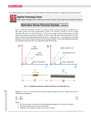
Fig. 1.7 shows the behavioral similarity of an electric resistor and the resistivity of a hydraulic line.
The figure shows the linear proportionality between the electrical current I and the voltage
difference ∆ ∆∆ ∆V across an electrical resistor. For the same voltage, small resistance passes electrical
current larger than largr resistance. Similarly, the figure shows the linear proportionality between the
fluid flow Q and the differential pressure ∆ ∆∆ ∆p across a hydraulic line. A hydraulic line with large
diameter is less resistive than a hydraulic line with small diameter. So, for same differential pressure,
large diameter line passes flow rate larger than small diameter line.
Fig. 1.7 - Similarity Characteristics of Electrical Resistance and Hydraulic Lines
78 Equations 1.3 and 1.4 confirm the linear proportionality between the effort variable and the flow
Variable in both elements.
∆ = .
∆ = .
Where:
R is the resistance that depends on the dimensional parameter of the resistive element.
Electrical resistance has the units of Ohm (Ω).
Hydraulic line resistance has the units of [bar / (lit/min)].
www.ghmediabusiness.com
| Global MDA Journal | NOV-DEC 2017