
Page 321 - APPLIED PROCESS DESIGN FOR CHEMICAL AND PETROCHEMICAL PLANTS, Volume 1, 3rd Edition
P. 321
Mixing of Liquids 289
i I .,.._
Shope Relationships for
ToM� ......
r+: Viscosity ,Cenlipoises---J Selection Chart ,. Turbine Desl9ns
,.
Solid
ond
Mixing Device 102 103 104 105 Plastic State Service l�!X.!09 Ranoe Criteria Dlo Rollo Dlo.:,1� Pooition
bnptlltr
Stale
Air Aaitotlon --- -- Paddle ... I.Volume 3:1 Unlinited Sintlt or
_
Turbine
Liouid Jets - - Blendin9 Propeller Clrculalion to 6:1 Multlpto
i Paddles i- - • --
Tonk Vol.
Pronellers ...... � Di spm ion PropeJer ... 1,000,000 Gals .
Turbines -- --· ---- Turbine I.Drop Size 3.0:1 1:1 At/orBtlow
Control
Center Lint
Cones ...... _ 2.Re·Circu· to 3.5:! 1:2 in of Liq..14
Stog1d
D!sks --· --- - -- (Immiscible Paddle lallor. Mixers Chori•
Systems)
Screws - Flow � t,000 Gals./Mln .
Barrels i--- Reactions Turbine I. Intensity 2.5:1 1:1 510911 ot
Multlplo
2.Volume
to3.5:I to 3:1
Ball Mills -· --- In Solution Propeller Circulollon
Ribbons (Miscible Paddle
Systems!
-
Kneaders -- -- - ChargeVd. 20,000 Gals. Al/o,BtlDW
I.Sheer
--- -
Colloid Mills i--- Turbine - 2.Volume 1.6 :1 I :2 CutarUnt
103.2:1 to 2:1
Soeciol Mills Dissolution Propeller Circulation ol lkauld
Cho,91
Mu lie rs Paddle 10000 Gals.
ChoroeV
=::
Pua Mills --- -- - -·-· Turbine I.Circulation 2.0:1 1:1
Internal Mixers Solids - to3.5:I to 1:2 t.tm�o;o ... ,.,
2.Velocily
Roll Mills - Suspension Propeller 2.0n Botto,o
on Bottom
Paddle
Conical Mills %Soids - 100% 0
Pan Mills ---- Propelltr .. I.Controlled 2.5:t 4:1 l � -lowolf
Turbine
lmoact Wheels Gos Shear to4.0:I to 1:1 o,.. lff
D�-Ofl
Botto111
Batch Process
- Applications Paddle 2.Clrculotion z.5,11-11111,ct,
Key = - ·- Continuous Process Gos Vol. - 3.Hi � h tust Btlow
Ve ocily
5 000 cu. ff./mln.
'-"•Id lmf
Turbine I.Volume 1.5 :, ,:2 Sln9l1 o,
Hi9h
Clrculotion to 2.s:1 to 2:1 Mu!Mplo
Figure 5-1. Range of operation of mixers. By permission, Quillen, Viscosity Propeller • -
2.Low
�- S., Chem. Engr., June 1954, p. 177 [15]. Applications Poddle Velocity I
Vis. 1,000,000 c.ps ....
Poddle ..... I.Volume Reloted Depends
Turbine
Circulation lo Other onOlher Multlpl1 1
Heot Propeller lmPtlW:r I
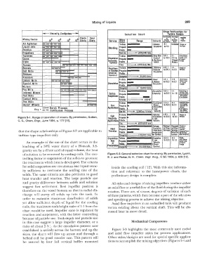
that the shape relationships of Figure 5-2 are applicable to Transfer 2.HIQh Veloc. Stlvlces Ser � 0p,..u,1- .....
Across Trans·
ll!in9
hrSu<foco
turbine type impellers only. ChoroeV .. 20,000 Gals. fer Surface formed """''"'"c.ib
Crysta Rizo· Turbine 1.Clrculalion 2.0:1 2:1 5�911,
At/or Btlo•
2.Low
An example of the use of the chart occurs in the lion Propeller 3.Shear ·� 3.2:1 to 1:1 Center Lint I
. Velocity
or
ol li4uld
Alddle
leaching of a 50% water slurry of a 20-mesh, 3.8- Precipitation Charge� 20,000 Gols. Control °'"'it
gravity ore by a dilute acid of equal volume, the heat
or solution to be removed by cooling coils. The con- Figure 5-2. General selection chart for mixing. By permission, Lyons,
trolling factor is suspension of the solids to promote E. J. and Parker, N. H., Chem. Engr. Prog., V. 50, 1954, p. 629 [12].
the reaction in which heat is developed. The criteria
for solid suspension are circulation and liquid veloc- inside the cooling coil [12]. With this size informa-
ity sufficient to overcome the settling rate of the tion and reference to the horsepower charts, the
solids. The same criteria are also pertinent to good preliminary design is complete.
heat transfer and reaction. The large particle size
and gravity difference between solids and solution All styles and designs of mixing impellers produce either
suggest fast settlement. Best impeller position is an axial-flow or a radial-flow of the fluid during the impeller
therefore on the vessel bottom so that its radial dis- rotation. There are, of course, degrees of variation of each
charge will sweep all solids up into the tank. In of these patterns, which then become a pan of the selection
order to maintain rnaxirnurn distribution of solids and specifying process to achieve the mixing objective.
yet allow sufficient depth of liquid for the cooling Axial flow impellers in an unbaffled tank will produce
coils, the maximum tank-height ratio of 1:1 from the vortex swirling about the vertical shaft. This will be dis-
chart would be used. Impeller ratio is regulated by cussed later in more detail.
reaction and suspension, with the latter controlling
because of particle size. Tank depth and particle size
in this case suggest a large impeller diameter, or a Mechanical Components
ratio of about 2.5:�. As the circulation pattern now
established is radially across the bottom and up the Figure 5-3 highlights the most commonly used radial
sides, the slurry will flow up across and through a and axial flow impeller styles for process applications.
helical coil for good transfer rate. This pattern will Other styles/ designs are used for special specific applica-
be assured by four Iull vertical baffles mounted tions to accomplish the mixing objectives (Figures 5-4 and