
Page 69 - APPLIED PROCESS DESIGN FOR CHEMICAL AND PETROCHEMICAL PLANTS, Volume 1, 3rd Edition
P. 69
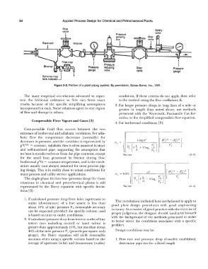
54                        Applied  Process Design for Chemical and  Petrochemical Plants

                                      Stop
                                      valve                                                  Safety
                                                                                             valve
                                        i                             Pressure
                                                                      sensing
                                                                      line
                                                                        l


                                                               Pressure
                                                     Pressure   reducing          Stop                  Pressure
                          Spira-tee trap J                     valve              valve                gauge
                                                     gauge

                          leak indicator
                                 Figure 2-2.  Portion of a plant piping system.  By permission,  Spirax-Sarco,  Inc.,  1991.


               The  many  empirical  correlations  advanced  to  repre-   conditions.  If these criteria do  not apply,  then refer
             sent  the  frictional  resistance  to  flow  vary  from  exact   to the method using the flow coefficient,  K.
             results  because  of the  specific  simplifying  assumptions   3. For larger pressure drops  in long lines  of a  mile or
             incorporated in each. Some relations agree in one region   greater  in  length  than  noted  above,  use  methods
             of flow and diverge in others.                            presented  with  the Weymouth,  Panhandle  Gas  for-
                                                                       mulas, or the simplified compressible flow equation.
                    Compressible Flow:  Vapors and Gases  [3]
                                                                     4.  For isothermal conditions  [31:
               Compressible  fluid  flow  occurs  between  the  two
             extremes of isothermal and adiabatic conditions. For adia-
             batic  flow  the  temperature  decreases  (normally)  for
             decreases in pressure, and the condition is represented by
             p'V'(k)  = constant. Adiabatic flow is often assumed in short
             and  well-insulated  pipe,  supporting  the  assumption  that
             no heat is transferred to or from the pipe contents, except   lbs/sec                               (2-3)
             for  the  small  heat  generated  by  friction  during  flow.
             Isothermal p'Va  =  constant temperature, and is the mech-
             anism  usually  (not always)  assumed for most process  pip-
             ing design.  This is in reality close to actual conditions for
             many process and utility service applications.
               The single-phase friction loss  (pressure drop)  for these
             situations  in  chemical  and  petrochemical  plants  is  still
             represented  by  the  Darcy  equation  with  specific  limita-   lbs/sec                            (2-4)
             tions  [3]:

                1. If calculated pressure drop from inlet (upstream)  to   The correlations included here are believed to apply to
                  outlet  (downstream)  of a  line  system  is  less  than   good  plant  design  procedures  with  good  engineering
                  about 10% of inlet pressure P 1, reasonable accuracy
                  can be  expected provided  the specific volume used   accuracy.  As a matter of  good practice with the exercise of
                                                                   proper  judgment,  the designer should familiarize himself
                  is based on inlet or outlet conditions.
               2. If  calculated pressure drop from inlet lo outlet of  line   with  the  background of the methods  presented in order
                                                                   to  better select the  conditions  associated with  a  specific
                  system  (not  including  control  or  hand  valves)  is   problem.
                  greater than approximately  10%, but less than about
                  40% of the inlet pressure P1  (pounds per square inch   Design conditions may be:
                  gauge),  the  Darcy  equation  will  yield  reasonable
                  accuracy when  using a  specific volume based on the   1. Flow  rate  and  pressure  drop  allowable  established,
                  average of upstream  (inlet)  and downstream (outlet)   determine pipe size for a fixed length