
Page 199 - REPOWER REFERENCE GUIDE (2020)
P. 199
Exhaust System Installation Requirements—Sterndrive Applications
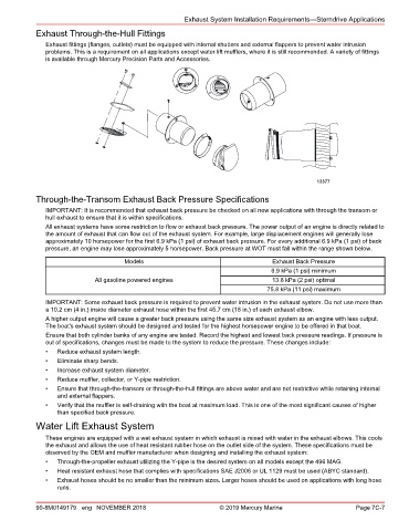
Exhaust Through‑the‑Hull Fittings
Exhaust fittings (flanges, outlets) must be equipped with internal shutters and external flappers to prevent water intrusion
problems. This is a requirement on all applications except water lift mufflers, where it is still recommended. A variety of fittings
is available through Mercury Precision Parts and Accessories.
13377
Through‑the‑Transom Exhaust Back Pressure Specifications
IMPORTANT: It is recommended that exhaust back pressure be checked on all new applications with through the transom or
hull exhaust to ensure that it is within specifications.
All exhaust systems have some restriction to flow or exhaust back pressure. The power output of an engine is directly related to
the amount of exhaust that can flow out of the exhaust system. For example, large displacement engines will generally lose
approximately 10 horsepower for the first 6.9 kPa (1 psi) of exhaust back pressure. For every additional 6.9 kPa (1 psi) of back
pressure, an engine may lose approximately 5 horsepower. Back pressure at WOT must fall within the range shown below.
Models Exhaust Back Pressure
6.9 kPa (1 psi) minimum
All gasoline powered engines 13.8 kPa (2 psi) optimal
75.8 kPa (11 psi) maximum
IMPORTANT: Some exhaust back pressure is required to prevent water intrusion in the exhaust system. Do not use more than
a 10.2 cm (4 in.) inside diameter exhaust hose within the first 45.7 cm (18 in.) of each exhaust elbow.
A higher output engine will cause a greater back pressure using the same size exhaust system as an engine with less output.
The boat's exhaust system should be designed and tested for the highest horsepower engine to be offered in that boat.
Ensure that both cylinder banks of any engine are tested. Record the highest and lowest back pressure readings. If pressure is
out of specifications, changes must be made to the system to reduce the pressure. These changes include:
• Reduce exhaust system length.
• Eliminate sharp bends.
• Increase exhaust system diameter.
• Reduce muffler, collector, or Y‑pipe restriction.
• Ensure that through‑the‑transom or through‑the‑hull fittings are above water and are not restrictive while retaining internal
and external flappers.
• Verify that the muffler is self‑draining with the boat at maximum load. This is one of the most significant causes of higher
than specified back pressure.
Water Lift Exhaust System
These engines are equipped with a wet exhaust system in which exhaust is mixed with water in the exhaust elbows. This cools
the exhaust and allows the use of heat resistant rubber hose on the outlet side of the system. These specifications must be
observed by the OEM and muffler manufacturer when designing and installing the exhaust system:
• Through‑the‑propeller exhaust utilizing the Y‑pipe is the desired system on all models except the 496 MAG.
• Heat resistant exhaust hose that complies with specifications SAE J2006 or UL 1129 must be used (ABYC standard).
• Exhaust hoses should be no smaller than the minimum sizes. Larger hoses should be used on applications with long hose
runs.
90-8M0149179 eng NOVEMBER 2018 © 2019 Mercury Marine Page 7C-7