
Page 374 - REPOWER REFERENCE GUIDE (2020)
P. 374
Testing the Exhaust System
Checking by Drilling and Tapping Exhaust Manifolds
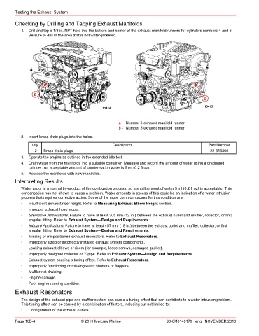
1. Drill and tap a 1/8 in. NPT hole into the bottom and center of the exhaust manifold runners for cylinders numbers 4 and 5.
Be sure to drill in the area that is not water‑jacketed.
a
b
13415
13414
a - Number 4 exhaust manifold runner
b - Number 5 exhaust manifold runner
2. Insert brass drain plugs into the holes.
Qty. Description Part Number
2 Brass drain plugs 22‑818390
3. Operate the engine as outlined in the extended idle test.
4. Drain water from the manifolds into a suitable container. Measure and record the amount of water using a graduated
cylinder. An acceptable amount of condensation water is 5 ml (0.2 fl oz).
5. Replace the manifolds with new manifolds.
Interpreting Results
Water vapor is a normal by‑product of the combustion process, so a small amount of water 5 ml (0.2 fl oz) is acceptable. This
condensation has not shown to cause a problem. Water amounts in excess of this could be an indication of a water intrusion
problem that requires corrective action. Some of the more common causes for this condition are:
• Insufficient exhaust riser height. Refer to Measuring Exhaust Elbow Height section.
• Improper exhaust hose slope.
• Sterndrive Applications: Failure to have at least 305 mm (12 in.) between the exhaust outlet and muffler, collector, or first
angular fitting. Refer to Exhaust System—Design and Requirements.
• Inboard Applications: Failure to have at least 457 mm (18 in.) between the exhaust outlet and muffler, collector, or first
angular fitting. Refer to Exhaust System—Design and Requirements.
• Missing or mispositioned exhaust resonators. Refer to Exhaust Resonators.
• Improperly sized or incorrectly installed exhaust system components.
• Leaking exhaust elbows or risers (for example, loose screws, damaged gasket).
• Improperly designed collector or Y‑pipe. Refer to Exhaust System—Design and Requirements.
• Exhaust system causing a tuning effect. Refer to Exhaust Resonators.
• Improperly functioning or missing water shutters or flappers.
• Muffler not draining.
• Engine damage.
• Poor engine running condition.
Exhaust Resonators
The design of the exhaust pipe and muffler system can cause a tuning effect that can contribute to a water intrusion problem.
This tuning effect can be caused by a combination of factors, including but not limited to:
• Configuration of the exhaust outlets.
Page 10B-4 © 2019 Mercury Marine 90-8M0149179 eng NOVEMBER 2018