
Page 311 - Toro Irrigation Product Catalogue August 2020
P. 311
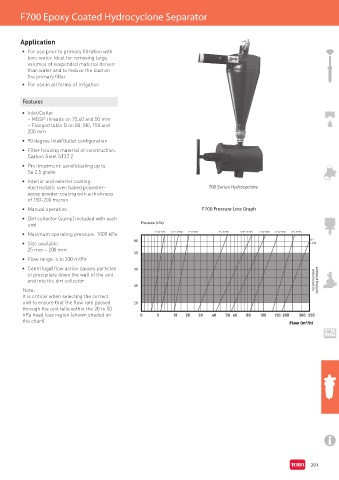
F700 Epoxy Coated Hydrocyclone Separator


        Application

         •  For use prior to primary filtration with
           bore water. Ideal for removing large
           volumes of suspended material denser
           than water and to reduce the load on
           the primary filter
         •  For use in all forms of irrigation


         Features
         •  Inlet/Outlet
           – MBSP threads on 25,40 and 50 mm
           – Flanged table D on 80,100, 150 and
           200 mm
         •  90 degree Inlet/Outlet configuration
         •  Filter housing material of construction:
           Carbon Steel ST37.2
         •  Pre-treatment: sand blasting up to
           Sa 2.5 grade
         •  Interior and exterior coating:
           electrostatic oven baked polyester-                            700 Series Hydrocyclone
           epoxy powder coating with a thickness
           of 150-200 micron
         •  Manual operation                                            F700 Pressure Loss Graph
         •  Dirt collector (sump) included with each
           unit                                   Pressure (kPa)

         •  Maximum operating pressure: 1000 kPa        1”>F720  1.5”>F730  2”>F740  3”>F750  3”4”>F755  4”>F760  6”>F770  6”>F775
         •  Size available                      60                                                            8”>
                                                                                                              F780
           25 mm – 200 mm
                                                50
         •  Flow range: 4 to 330 m³/hr
         •  Centrifugal flow action causes particles   40
           to precipitate down the wall of the unit
           and into the dirt collector
                                                30
         Note:
         It is critical when selecting the correct
         unit to ensure that the flow rate passed   20
         through the unit falls within the 20 to 50
         kPa head loss region (shown shaded on
         the chart).


                                                                                                              291