
Page 21 - E BOOK ENGINE MECHANICAL M2
P. 21
3. TURBOCHARGER
1. OUTLINES
The output of an engine can be increased by increasing the amount of air-fuel mixture drawn into the
cylinder and setting the engine operational parameters, like ignition timing to correspond to the in-
crease accordingly. The supercharger is the component responsible for increasing the amount of air
into the cylinder.
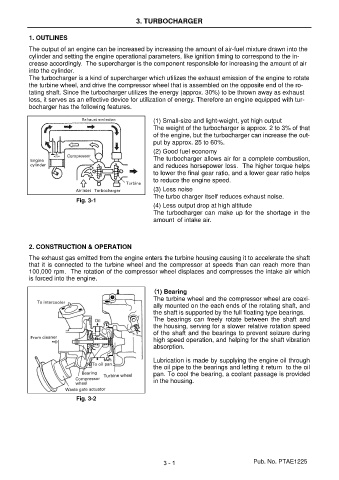
The turbocharger is a kind of supercharger which utilizes the exhaust emission of the engine to rotate
the turbine wheel, and drive the compressor wheel that is assembled on the opposite end of the ro-
tating shaft. Since the turbocharger utilizes the energy (approx. 30%) to be thrown away as exhaust
loss, it serves as an effective device for utilization of energy. Therefore an engine equipped with tur-
bocharger has the following features.
(1) Small-size and light-weight, yet high output
The weight of the turbocharger is approx. 2 to 3% of that
of the engine, but the turbocharger can increase the out-
put by approx. 25 to 60%.
(2) Good fuel economy
The turbocharger allows air for a complete combustion,
and reduces horsepower loss. The higher torque helps
to lower the final gear ratio, and a lower gear ratio helps
to reduce the engine speed.
(3) Less noise
The turbo charger itself reduces exhaust noise.
Fig. 3-1
(4) Less output drop at high altitude
The turbocharger can make up for the shortage in the
amount of intake air.
2. CONSTRUCTION & OPERATION
The exhaust gas emitted from the engine enters the turbine housing causing it to accelerate the shaft
that it is connected to the turbine wheel and the compressor at speeds than can reach more than
100,000 rpm. The rotation of the compressor wheel displaces and compresses the intake air which
is forced into the engine.
( (( (1) Bearing
The turbine wheel and the compressor wheel are coaxi-
ally mounted on the each ends of the rotating shaft, and
the shaft is supported by the full floating type bearings.
The bearings can freely rotate between the shaft and
the housing, serving for a slower relative rotation speed
of the shaft and the bearings to prevent seizure during
high speed operation, and helping for the shaft vibration
absorption.
Lubrication is made by supplying the engine oil through
the oil pipe to the bearings and letting it return to the oil
pan. To cool the bearing, a coolant passage is provided
in the housing.
Fig. 3-2
3 - 1 Pub. No. PTAE1225