
Page 154 - Sec 97
P. 154
หมวดที่ อุปกรณสำหรับชวยกันตกจากการทำงานที่สูง
97 HIGH SYSTEM LIFELINE
KeeGuard Components EN 13374 & EN 14122-3
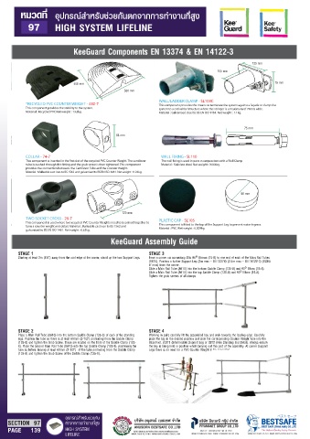
125 mm
100 mm
400 mm 75 mm
500 mm
WALL/LADDER CLAMP - SL109C
*RECYCLED PVC COUNTER WEIGHT - 440-7 This component provides the means to terminate the system against a façade or clamp the
This component provides the stability to the system. system to a cat ladder/structure where the stringer is a maximum of 70mm wide.
Material : Recycled PVC Net weight : 13.3kg. Material : Galvanised steel to BS EN ISO 1461. Net weight : 1.1kg.
75 mm
65 mm
COLLAR - 74-7 WALL FIXING - SL110
Material : Stainless steel. Net weight : 0.064kg.
provides the connection between the Cantilever Tube and the Counter Weight.
Material : Malleable cast iron to BS 1562 and galvanised to BS EN ISO 1461. Net weight : 0.24kg.
50 mm
120 mm
TWO SOCKET CROSS - 26-7 PLASTIC CAP - SL105
This component is used where two recycled PVC Counter Weights need to be joined together to
form a counter weight end detail. Material : Malleable cast iron to BS 1562 and Material : PVC. Net weight : 0.009kg.
galvanised to BS EN ISO 1461. Net weight : 0.63kg.
KeeGuard Assembly Guide
STAGE 1 STAGE 3
Starting at least 2m (6’6”) away from the roof edge at the corner, stand up the two Support Legs. Form a corner via connecting 2No 90º Elbows (15-8) to one end of each of the Main Rail Tubes
(8610). Position a further Support Leg (3m max – EN 13374) (2.4m max – EN 14122-3) (OSHA
8’ max) from the corner.
Slide a Main Rail Tube (8610) into the bottom Saddle Clamp (135-8) and 90º Elbow (15-8).
Slide a Main Rail Tube (8610) into the top Saddle Clamp (135-8) and 90º Elbow (15-8).
Tighten the grub screws of all clamps.
STAGE 2 STAGE 4
Place a Main Rail Tube (8610) into the bottom Saddle Clamp (135-8) of each of the standing Working in pairs carefully lift the assembled bay and walk towards the leading edge. Carefully
legs. Position the tube so there is at least 60mm (2-1/2”) protruding from the Saddle Clamp place the bay in the desired position and slide the corresponding Counter Weight tube into the
(135-8) and tighten the Grub Screw. These are located on the front of the Saddle Clamp (135- Base Foot. (CBT1 (Intermediate Support Leg or CBT2 (Free Standing End Detail). Always ensure
8). Place the second Main Rail Tube (8610) into the top Saddle Clamp (135-8), positioning the the bay is being held in position whist carrying out this part of the assembly. At corner Support
tube as before, leaving at least 60mm (2-1/2”) of the tube protruding from the Saddle Clamp Legs there is no need for a PVC Counter Weight to be connected.
(135-8) and tighten the Grub Screw of the Saddle Clamp (135-8).
อุปกรณสำหรับชวยกัน ϕετηʔϑ
SECTION 97 ตกจากการทำงานที่สูง บริษัท ปยะมณี กรุป จำกัด BESTSAFE
PIYAMANEE GROUP CO.,LTD
PAGE 139 HIGH SYSTEM ผูนำเขา ผูผลิต และจัดจำหนายสินคาประเภทอุปกรณเซฟตี้แบบครบวงจร SAFETY TECHNOLOGY WITH YOU BEST SAFE (THAILAND) CO.,LTD
LIFELINE WWW.THAIPPE.COM | WWW.ANUSORNBESTSAFE.COM WWW.PIYAMANEE.COM | WWW.PIYAMANEEGROUP.COM WWW.BESTSAFE.CO.TH | WWW.BESTSAFEPRODUCTS.COM