
Page 50 - Advanced Course
P. 50
KNX ADVANCED COURSE
When the heating is switched on, the system behaves as if it has a time delay. Slow
heating or cooling systems cannot be controlled via two-step control as it can lead to an
extreme overshoot and therefore a considerable loss of comfort.
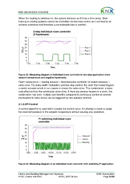
2-step individual room controller
(3°hysteresis)
35
30
25
°C, 20 Row 1
on/ 15 Row 2
off
10 Row 3
5
0
7:12 7:19 7:26 7:33 7:40 7:48
Time
Figure 22: Measuring diagram of individual room controller in two-step application (here
setpoint temperature and negative hysteresis)
Room temperature – heating actuator – thermoelectric controller (or switch actuator) –
valve drive. For pulse width modulation and two-step control, the room thermostat triggers
a switch actuator which in turn opens or closes the valve drive. This combination is more
cost-effective than the continuous valve drive. If there are several heaters in a room, this
combination has even multiple cost benefits compared to continuous control as several
thermoelectric valve drives can be triggered by one actuator channel.
2.1.2.2 PI Control
A control algorithm is used which creates the control value. An attempt is made to adapt
the room temperature to the setpoint temperature without causing any oscillation.
PI switching individual room
controller
35
30
25
°C, 20 Setpoint
e/a 15 Actual
10 Heating
5
0
9:21 9:36 9:50 10:04 10:19 10:33 10:48
Time
Figure 23: Measuring diagram of an individual room controller with switching PI application
Home and Building Management Systems KNX Association
HVAC Control with KNX HVAC_E0813b.doc Page 24/60