
Page 55 - Digital Electronics by harish
P. 55
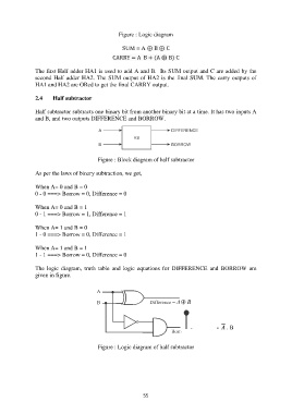
Figure : Logic diagram

                                                   SUM = A ⊕ B ⊕ C

                                               CARRY = A  B + (A ⊕ B) C

               The first Half adder HA1 is used to add A and B.  Its SUM output and C are added by the
               second Half adder HA2. The SUM output of HA2 is the final SUM. The carry outputs of
               HA1 and HA2 are ORed to get the final CARRY output.

               2.4     Half subtractor

               Half subtractor subtracts one binary bit from another binary bit at a time. It has two inputs A
               and B, and two outputs DIFFERENCE and BORROW.


                                         Figure : Block diagram of half subtractor

               As per the laws of binary subtraction, we get,

               When A= 0 and B = 0
               0 - 0 ===> Borrow = 0, Difference = 0

               When A= 0 and B = 1
               0 - 1 ===> Borrow = 1, Difference = 1

               When A= 1 and B = 0
               1 - 0 ===> Borrow = 0, Difference = 1

               When A= 1 and B = 1
               1 - 1 ===> Borrow = 0, Difference = 0

               The  logic  diagram,  truth  table  and  logic  equations  for  DIFFERENCE  and  BORROW  are
               given in figure.


                                                                                 Borrow =   . B


                                         Figure : Logic diagram of half subtractor


                                                           55