
Page 57 - Digital Electronics by harish
P. 57
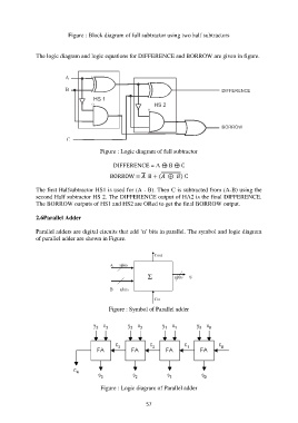
Figure : Block diagram of full subtractor using two half subtractors


               The logic diagram and logic equations for DIFFERENCE and BORROW are given in figure.


                                         Figure : Logic diagram of full subtractor

                                              DIFFERENCE = A ⊕ B ⊕ C

                                             BORROW =   B + (  ⊕  ) C

               The first Halfsubtractor HS1 is used for (A - B). Then C is subtracted from (A-B) using the
               second Half subtractor HS 2. The DIFFERENCE output of HA2 is the final DIFFERENCE.
               The BORROW outputs of HS1 and HS2 are ORed to get the final BORROW output.

               2.6Parallel Adder

               Parallel adders are digital circuits that add „n‟ bits in parallel. The symbol and logic diagram
               of parallel adder are shown in Figure.


                                             Figure : Symbol of Parallel adder


                                         Figure : Logic diagram of Parallel adder


                                                           57