
Page 126 - CarrLaneCatalog_2019ed-c.pdf
P. 126
ADJUSTABLE-TORQUE THUMB SCREWS
SCREW: 12L14 STEEL, CARBURIZED-HARDENED, BLACK OXIDE FINISH
KNOB: 12L14 STEEL, BLACK OXIDE FINISH
SPRING: MUSIC WIRE
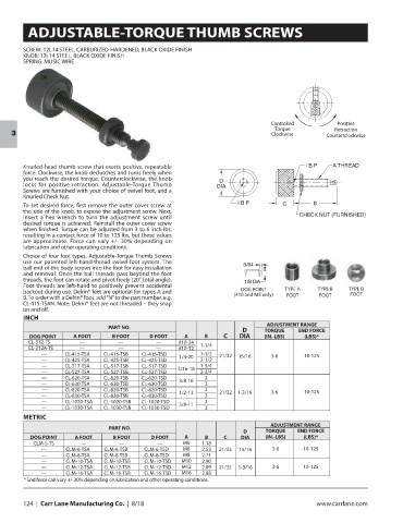
Controlled Positive
Torque Retraction
Clockwise
3 Counterclockwise
Knurled-head thumb screw that exerts positive, repeatable
force. Clockwise, the knob declutches and turns freely when
you reach the desired torque. Counterclockwise, the knob
locks for positive retraction. Adjustable-Torque Thumb
Screws are furnished with your choice of swivel foot, and a
Knurled Check Nut.
To set desired force, first remove the outer cover screw at
the side of the knob, to expose the adjustment screw. Next,
insert a hex wrench to turn the adjustment screw until
desired torque is achieved. Reinstall the outer cover screw
when finished. Torque can be adjusted from 3 to 6 inch-lbs,
resulting in a contact force of 10 to 125 lbs, but these values
are approximate. Force can vary +/- 30% depending on
lubrication and other operating conditions.
Choice of four foot types. Adjustable-Torque Thumb Screws
use our patented left-hand-thread swivel-foot system. The
ball end of the body screws into the foot for easy installation
and removal. Once the ball threads pass beyond the foot
threads, the foot can rotate and pivot freely (20° total angle).
Foot threads are left-hand to positively prevent accidental TYPE A TYPE B TYPE D
DOG POINT
backout during use. Delrin® feet are optional for types A and (#10 and M5 only) FOOT
B. To order with a Delrin® foot, add “N” to the part number, e.g. FOOT FOOT
CL-415-TSAN. Note: Delrin® feet are not threaded – they snap
on and off.
INCH
ADJUSTMENT RANGE
PART NO.
D TORQUE END FORCE
DOG POINT A FOOT B FOOT D FOOT A B C DIA (IN.-LBS) (LBS)*
CL-312-TS — — — #10-24
CL-312A-TS — — — #10-32 1-1/4
— CL-415-TSA CL-415-TSB CL-415-TSD 1-1/2 21/32 15/16 3-6 10-125
— CL-425-TSA CL-425-TSB CL-425-TSD 1/4-20 2-1/2
— CL-517-TSA CL-517-TSB CL-517-TSD 1-3/4
— CL-527-TSA CL-527-TSB CL-527-TSD 5/16-18 2-3/4
— CL-620-TSA CL-620-TSB CL-620-TSD 2
— CL-630-TSA CL-630-TSB CL-630-TSD 3/8-16 3
— CL-820-TSA CL-820-TSB CL-820-TSD 2 21/32 3-6 10-125
— CL-830-TSA CL-830-TSB CL-830-TSD 1/2-13 3 1-3/16
— CL-1020-TSA CL-1020-TSB CL-1020-TSD 2
— CL-1030-TSA CL-1030-TSB CL-1030-TSD 5/8-11 3
METRIC
ADJUSTMENT RANGE
PART NO.
D TORQUE END FORCE
DOG POINT A FOOT B FOOT D FOOT A B C DIA (IN.-LBS) (LBS)*
CLM-5-TS — — — M5 1.18
— CLM-6-TSA CLM-6-TSB CLM-6-TSD M6 2.53 21/32 15/16 3-6 10-125
— CLM-8-TSA CLM-8-TSB CLM-8-TSD M8 2.71
— CLM-10-TSA CLM-10-TSB CLM-10-TSD M10 2.90
— CLM-12-TSA CLM-12-TSB CLM-12-TSD M12 2.89 21/32 1-3/16 3-6 10-125
— CLM-16-TSA CLM-16-TSB CLM-16-TSD M16 2.88
* End force can vary +/-30% depending on lubrication and other operating conditions.
124 | Carr Lane Manufacturing Co. | 8/18 www.carrlane.com