
Page 171 - CarrLaneCatalog_2019ed-c.pdf
P. 171
BALL PLUNGERS
TYPES
STANDARD, STEEL BALL
Self-contained ball-and-spring device available in many sizes and forces. Locking element holds the unit
securely in place after installation. Install and/or adjust from either end.
STANDARD, DELRIN® BALL
Self-contained ball-and-spring device available in many sizes and forces. Locking element holds the unit
securely in place after installation. Install and/or adjust from either end. 4
PRESS FIT
Simple, economical spring-loaded plunger ideal for installation in softer materials, such as aluminum,
wood, or plastic. Sturdy shoulder provides a fixed seating position.
SELF-RETAINING
Due to their self-retaining design, these press-fit ball plungers can be securely installed in an ordinary
drilled hole. The slotted end of the thermoplastic body expands to compensate for hole tolerances up to
.008” oversize.
TECHNICAL INFORMATION
INSTALLATION:
To obtain full locking torque, countersink the installation hole to avoid cutting
the locking element. Countersink at a 90-100° angle to a diameter 1/32” larger
than the major thread diameter. Then, as you screw the plunger into its hole,
the locking element will be compressed, not cut. INFO+: See page 171 for
plunger wrenches.
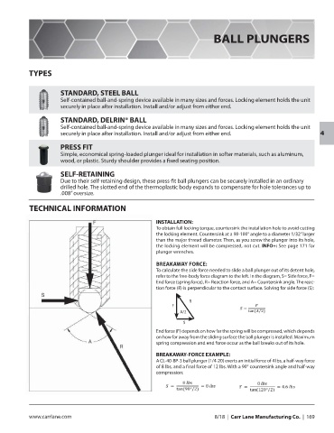
BREAKAWAY FORCE:
To calculate the side force needed to slide a ball plunger out of its detent hole,
refer to the free-body force diagram to the left. In the diagram, S= Side force, F=
End force (spring force), R= Reaction force, and A= Countersink angle. The reac-
tion force (R) is perpendicular to the contact surface. Solving for side force (S):
R
F
A/2
S
End force (F) depends on how far the spring will be compressed, which depends
on how far away from the sliding surface the ball plunger is installed. Maximum
spring compression and end force occur as the ball breaks out of its hole.
BREAKAWAY-FORCE EXAMPLE:
A CL-40-BP-3 ball plunger (1/4-20) exerts an initial force of 4 lbs, a half-way force
of 8 lbs, and a final force of 12 lbs. With a 90° countersink angle and half-way
compression:
www.carrlane.com 8/18 | Carr Lane Manufacturing Co. | 169