
Page 302 - CarrLaneCatalog_2019ed-c.pdf
P. 302
ID CLAMPS
BODY: 12L14 STEEL, BLACK OXIDE FINISH
CENTER SCREW: ALLOY STEEL, BLACK OXIDE FINISH
MOUNTING SCREWS: ALLOY STEEL, BLACK OXIDE FINISH
7
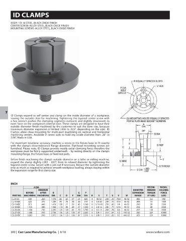
ID Clamps expand to self-center and clamp on the inside diameter of a workpiece,
leaving the outside clear for machining. Tightening the tapered center screw with
a hex wrench pushes the clamping segments outward, and slightly downward, to
exert force on the workpiece’s internal bore. These clamps are designed to have their
outside diameter finish machined by the customer to suit the bore size, because
maximum diameter expansion is limited (.006 to .025", depending on the size). ID
Clamps allow close mounting for multi-part machining on vertical and horizontal
machining centers. Available in seven sizes to hold any inside diameter from .26" to
2.06". Made in USA.
For maximum locational accuracy, machine a recess in the fixture base to fit exactly
with the clamp’s close-tolerance flange diameter. Flat-head mounting screws are
furnished. Please note, ID Clamps provide mostly radial clamping force; therefore the
workpiece must be firmly supported underneath – by resting directly on the clamp’s
mounting flange, the fixture base, or fixed rest pads.
Before finish machining the clamp’s outside diameter on a lathe or milling machine,
expand the clamp slightly (.002 - .003") from its relaxed diameter by tightening the
tapered center screw. Secure with a jam nut if necessary. Reduce the outside diameter
only as much as required to achieve smooth workpiece loading, always staying within
the expansion range for that clamp size.
INCH
A DIA RECOM- RADIAL
MINIMUM DIAMETER MENDED HOLDING
BEFORE AFTER B G P EXPANSION TORQUE FORCE
PART NO. MACHINING MACHINING DIA C D F DIA DIA R S T U V W RANGE (FT-LBS) (LBS)
CL-8-IDC .500 .260 1.170 .86 .63 .57 .24 .825 4 #8-32 .230 .29 7/64 #6-32 .006 3.6 950
CL-10-IDC .625 .370 1.240 .99 .76 .58 .36 .910 4 1/4-20 .230 .53 3/16 #6-32 .008 13 1900
CL-13-IDC .813 .440 1.476 1.00 .77 .59 .43 1.140 6 5/16-18 .230 .60 1/4 #6-32 .010 28 2500
CL-18-IDC 1.125 .580 1.968 1.14 .90 .69 .57 1.550 6 3/8-16 .245 .77 5/16 #8-32 .014 49 4500
CL-23-IDC 1.438 .710 2.205 1.25 1.00 .81 .70 1.790 6 1/2-13 .250 .78 3/8 #8-32 .017 120 5900
CL-27-IDC 1.688 .910 2.736 1.56 1.25 1.06 .87 2.200 6 5/8-11 .310 .84 1/2 #10-32 .020 224 10000
CL-33-IDC 2.063 .910 2.972 1.56 1.25 1.06 .87 2.515 6 5/8-11 .310 .85 1/2 #10-32 .025 224 10000
300 | Carr Lane Manufacturing Co. | 8/18 www.carrlane.com