Page 104 - MESCInstrumentationCatalogue
P. 104

TECHNICAL INFORMATION


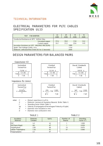
                ELECTRICAL  PARAMETERS  FOR  PLTC  CABLES
                SPECIFICATION  UL13


                                                                  22        20         18        16
                             TEST  PAR AMETERS
                                                                 AWG       AWG       AWG        AWG
                 Conductor Resistance at 20°C  (Ω/Km) Max.
                                             Uncoated copper     57.6      35.8       22.8      14.2
                                             Coated copper       59.7      37.2       23.6      14.9
                 Insulation Resistance at 20°C  (MΩ-Km) Min.(XLPE)              1000
                 Spark Test Voltage (Volts) r.m.s.                              1750
                 Dielectric withstand Test (Volts DC for 2 Seconds)             2500


                DESIGN PARAMETERS FOR BALANCED PAIRS


                  Capacitance (C)

                     Unshielded                          Shielded                    Overall Shielded &
                     Twisted Pair                      Twisted Pair                       Cabled
                        7.218      .                      12.14        .                   9.515        .
                =                                =                                =
                         1.3 (D)                           1.2 (D)                         1.5 (D)
                   Log                              Log                              Log
                          f (d)                             f (d)                            f (d)


               Impedance Zo (ohms)

                     Unshielded                          Shielded                    Overall Shielded &
                     Twisted Pair                      Twisted Pair                       Cabled

                       310                            276      1.2(D)                  347       1.5(D)
                    =                              =       Log                      =        Log
                          C
                                                                 f (d)                            f (d)


                where  C      =  Mutual capacitance in pF/m.
                              =  Dielectric constant of insulation Material  (Refer Table 1)
                       f      =  Stranding factor (Refer Table 2)
                       Vp     =   Velocity of propagation (Percentage of Velocity of Light)
                       D      =  Diameter over insulation in mm.
                       d      =  Diameter over conductor in mm.

                                    TABLE 1                                        TABLE 2

                  Insulation        Dielectric          Vp(%)            Number of           Stranding
                  Material          Constant                              Strands           Factor (f )
              PVC                      5.0                45                  1               1.000
              PVC(Semi-Rigid)          4.6                47                  7               0.939
              Polyethylene             2.26               66                 19               0.970
              Cellular Polyethylene    1.56               82                 37               0.980
              Polyproplyene            2.2                67


                                                                                                                 101
   99   100   101   102   103   104   105   106   107   108