
Page 236 - Robot Design Handbook ROBOCON Malaysia 2019
P. 236
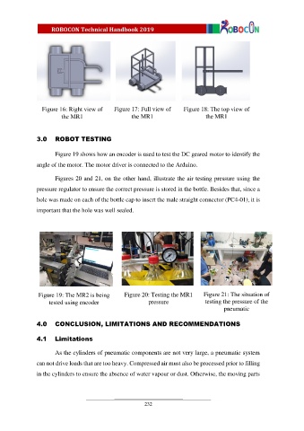
Figure 16: Right view of     Figure 17: Full view of    Figure 18: The top view of

                         the MR1                     the MR1                      the MR1


               3.0  ROBOT TESTING


                       Figure 19 shows how an encoder is used to test the DC geared motor to identify the
               angle of the motor. The motor driver is connected to the Arduino.


                       Figures 20 and 21, on the other hand, illustrate the air testing pressure using the
               pressure regulator to ensure the correct pressure is stored in the bottle. Besides that, since a

               hole was made on each of the bottle cap to insert the male straight connector (PC4-01), it is
               important that the hole was well sealed.


               .  Figure 19: The MR2 is being     Figure 20: Testing the MR1     Figure 21: The situation of
                    tested using encoder                   pressure              testing the pressure of the
                                                                                         pneumatic


               4.0  CONCLUSION, LIMITATIONS AND RECOMMENDATIONS


               4.1    Limitations

                       As the cylinders of pneumatic components are not very large, a pneumatic system

               can not drive loads that are too heavy. Compressed air must also be processed prior to filling
               in the cylinders to ensure the absence of water vapour or dust. Otherwise, the moving parts


                                                          232