
Page 24 - Jetpower (January 2020)
P. 24
022-025 Odyssey:Layout 1 Englisch 09.01.2020 13:43 Uhr Seite 24
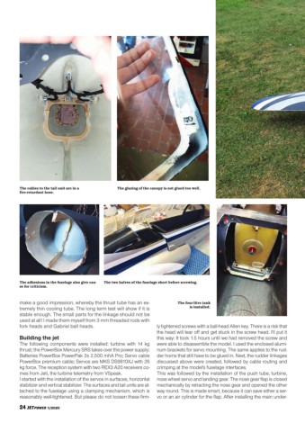
The cables to the tail unit are in a The glazing of the canopy is not glued too well.
fire-retardant hose.
The adhesions in the fuselage also give cau- The two halves of the fuselage short before screwing.
se for criticism.
make a good impression, whereby the thrust tube has an ex- The four-litre tank
tremely thin cooling tube. The long term test will show if it is is installed.
stable enough. The small parts for the linkage should not be
used at all! I made them myself from 3 mm threaded rods with
fork heads and Gabriel ball heads. ly tightened screws with a ball-head Allen key. There is a risk that
the head will tear off and get stuck in the screw head. I'll put it
Building the jet this way: It took 1.5 hours until we had removed the screw and
The following components were installed: turbine with 14 kg were able to disassemble the model. I used the enclosed alumi-
thrust; the PowerBox Mercury SRS takes over the power supply; num brackets for servo mounting. The same applies to the rud-
Batteries PowerBox PowerPak 2s 2,500 mhA Pro; Servo cable der horns that still have to be glued in. Next, the rudder linkages
PowerBox premium cable; Servos are MKS DS9910XJ with 26 discussed above were created, followed by cable routing and
kg force. The reception system with two REX3 A20 receivers co- crimping at the model's fuselage interfaces.
mes from Jeti, the turbine telemetry from VSpeak. This was followed by the installation of the push tube, turbine,
I started with the installation of the servos in surfaces, horizontal nose wheel servo and landing gear. The nose gear flap is closed
stabilizer and vertical stabilizer. The surfaces and tail units are at- mechanically by retracting the nose gear and opened the other
tached to the fuselage using a clamping mechanism, which is way round. This is made smart, because it can save either a ser-
reasonably well-tightened. But please do not loosen these firm- vo or an air cylinder for the flap. After installing the main under-
24 JETPOWER 1/2020