
Page 325 - The City and Guilds Textbook: Plumbing Book 1 for the Level 3 Apprenticeship (9189), Level 2 Technical Certificate (8202) and Level 2 Diploma (6035)
P. 325
Chapter 5 Cold water systems
The internal design of the valve allows water to be isolated by turning
a ball through 90°. The ball has a hole through it, which, when in line
with the direction of water flow, allows water to pass through it. It is
isolated when the hole is at 90° to the flow of water.
Drain-off valves p Figure 5.90 Internal workings of a spherical
Drain-off valves are small valves that are strategically placed at plug valve
low points in the installation to allow draining down of the system.
Several types are available:
● with a male thread to allow connection to low carbon steel pipes and fittings
● with a spigot end to facilitate connection to either copper capillary fittings
or compression fittings
● with or without a packing gland.
Drain-off valves should be positioned in accordance with the Water Supply
(Water Fittings) Regulations, which state that:
No drain valve should be placed below ground or in any position which
allows the valve to become submerged in water.
p Figure 5.91 A spherical plug valve
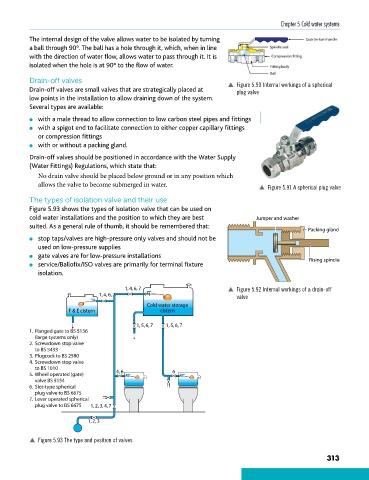
The types of isolation valve and their use
Figure 5.93 shows the types of isolation valve that can be used on
cold water installations and the position to which they are best Jumper and washer
suited. As a general rule of thumb, it should be remembered that:
Packing gland
● stop taps/valves are high-pressure only valves and should not be
used on low-pressure supplies
● gate valves are for low-pressure installations
● service/Ballofix/ISO valves are primarily for terminal fixture Rising spindle
isolation.
1, 4, 6, 7 p Figure 5.92 Internal workings of a drain-off
1, 4, 6, 7 valve
Cold water storage
F & E cistern cistern
1, 5, 6, 7 1, 5, 6, 7
1. Flanged gate to BS 5136
(large systems only)
2. Screwdown stop valve
to BS 5433
3. Plugcock to BS 2580
4. Screwdown stop valve
to BS 1010
5. Wheel operated (gate) 4, 6 6
valve BS 5154
6. Slot-type spherical
plug valve to BS 6675
7. Lever operated spherical
plug valve to BS 6675 1, 2, 3, 4, 7
1, 2, 3
p Figure 5.93 The type and position of valves
313
9781510416482.indb 313 29/03/19 8:59 PM