
Page 389 - The City and Guilds Textbook: Plumbing Book 1 for the Level 3 Apprenticeship (9189), Level 2 Technical Certificate (8202) and Level 2 Diploma (6035)
P. 389
Chapter 6 Hot water systems
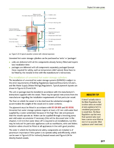
Balanced cold Isolation valve
Hot water draw-off water connection
In-line strainer
Pressure reducing valve
Internal expansion Check valve
pocket or air bubbles
Expansion (pressure)
relief valve
Flow Temperature relief valve
Heat exchanger D1 discharge pipework
Immersion heater Tundish
D2 discharge pipework
Return
Cold feed
p Figure 6.22 A typical unvented cylinder with internal expansion
Unvented hot water storage cylinders can be purchased as ‘units’ or ‘packages’:
● units are delivered with all the components already factory fitted and require
less installation time
● packages are delivered with all components separately packaged (except
those required for safety, such as temperature relief valves); these have to
be fitted by the installer in line with the manufacturer’s instructions.
The installation of unvented hot water storage cylinders
The installation of unvented hot water storage systems (UHWSS) is subject to
the strict requirements of Building Regulations Approved Documents G3 and L,
and the Water Supply (Water Fittings) Regulations. Typical pipework layouts are
shown in Figures 6.23 and 6.24.
The unit or package must be installed in accordance with the manufacturer’s
instructions supplied with the vessel. There may be special instructions from the INDUSTRY TIP
manufacturer regarding the installation requirements of that particular vessel.
It doesn’t actually state in
The floor on which the vessel is to be sited must be substantial enough to the Water Regulations that
accommodate the weight of the vessel and its water contents. isolation valves are needed
The pipework must be fitted in accordance with BS EN 806 and BS 8558. at every appliance but it is
Unvented hot water storage systems require at least a 22 mm cold water feed considered good practice
supplied by a water undertaker because of the high flow rate and pressure to install them. The Water
that the vessels operate at. Water can be supplied through a boosting pump Regulations say that every
float-operated valve must
and cold water accumulator if necessary (this will be discussed later in the have a service valve fitted as
chapter). A 22 mm hot water draw-off is required in all installations, but this near to it as possible. Other
may be reduced for particular appliances such as washbasins, sinks and bidets. appliances aren’t mentioned.
Isolation valves should be fitted at all appliances in line with good practice.
The order in which the functional and safety components are installed is of
paramount importance if the system is to operate safely and efficiently, which
can be seen in Figure 6.23 for indirectly heated vessels and Figure 6.24 for
directly heated vessels.
377
9781510416482.indb 377 29/03/19 9:01 PM