
Page 415 - The City and Guilds Textbook: Plumbing Book 1 for the Level 3 Apprenticeship (9189), Level 2 Technical Certificate (8202) and Level 2 Diploma (6035)
P. 415
Chapter 6 Hot water systems
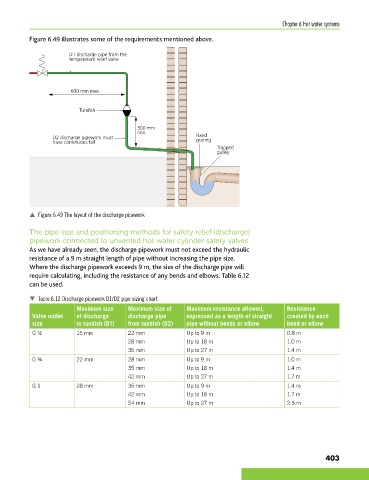
Figure 6.49 illustrates some of the requirements mentioned above.
D1 discharge pipe from the
temperature relief valve
600 mm max.
Tundish
300 mm
min.
D2 discharge pipework must Fixed
grating
have continuous fall
Trapped
gulley
p Figure 6.49 The layout of the discharge pipework
The pipe size and positioning methods for safety relief (discharge)
pipework connected to unvented hot water cylinder safety valves
As we have already seen, the discharge pipework must not exceed the hydraulic
resistance of a 9 m straight length of pipe without increasing the pipe size.
Where the discharge pipework exceeds 9 m, the size of the discharge pipe will
require calculating, including the resistance of any bends and elbows. Table 6.12
can be used.
Table 6.12 Discharge pipework D1/D2 pipe sizing chart
Maximum size Maximum size of Maximum resistance allowed, Resistance
Valve outlet of discharge discharge pipe expressed as a length of straight created by each
size to tundish (D1) from tundish (D2) pipe without bends or elbow bend or elbow
G ½ 15 mm 22 mm Up to 9 m 0.8 m
28 mm Up to 18 m 1.0 m
35 mm Up to 27 m 1.4 m
G ¾ 22 mm 28 mm Up to 9 m 1.0 m
35 mm Up to 18 m 1.4 m
42 mm Up to 27 m 1.7 m
G 1 28 mm 35 mm Up to 9 m 1.4 m
42 mm Up to 18 m 1.7 m
54 mm Up to 27 m 2.3 m
403
9781510416482.indb 403 29/03/19 9:02 PM