
Page 412 - The City and Guilds Textbook: Plumbing Book 1 for the Level 3 Apprenticeship (9189), Level 2 Technical Certificate (8202) and Level 2 Diploma (6035)
P. 412
The City & Guilds Textbook: Plumbing Book 1
ACTIVITY
Transposing the formula P V = P V as shown in the example on the previous
1 1
2 2
page, find the initial cold fill pressure of the expansion vessel and the final hot
operating pressure of the storage cylinder.
Where:
P = Initial pressure = 1.5 bar
1
V = Initial volume = 18 litres
1
P = Final pressure = to be found
2
V = Final volume = 18 litres − 9 litres of expanded water
2
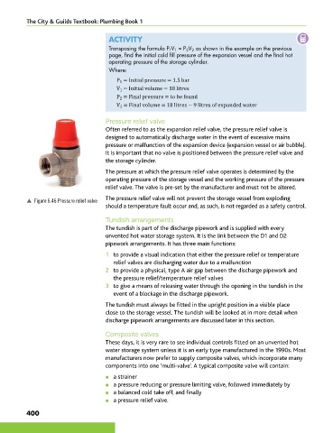
Pressure relief valve
Often referred to as the expansion relief valve, the pressure relief valve is
designed to automatically discharge water in the event of excessive mains
pressure or malfunction of the expansion device (expansion vessel or air bubble).
It is important that no valve is positioned between the pressure relief valve and
the storage cylinder.
The pressure at which the pressure relief valve operates is determined by the
operating pressure of the storage vessel and the working pressure of the pressure
relief valve. The valve is pre-set by the manufacturer and must not be altered.
p Figure 6.46 Pressure relief valve The pressure relief valve will not prevent the storage vessel from exploding
should a temperature fault occur and, as such, is not regarded as a safety control.
Tundish arrangements
The tundish is part of the discharge pipework and is supplied with every
unvented hot water storage system. It is the link between the D1 and D2
pipework arrangements. It has three main functions:
1 to provide a visual indication that either the pressure relief or temperature
relief valves are discharging water due to a malfunction
2 to provide a physical, type A air gap between the discharge pipework and
the pressure relief/temperature relief valves
3 to give a means of releasing water through the opening in the tundish in the
event of a blockage in the discharge pipework.
The tundish must always be fitted in the upright position in a visible place
close to the storage vessel. The tundish will be looked at in more detail when
discharge pipework arrangements are discussed later in this section.
Composite valves
These days, it is very rare to see individual controls fitted on an unvented hot
water storage system unless it is an early type manufactured in the 1990s. Most
manufacturers now prefer to supply composite valves, which incorporate many
components into one ‘multi-valve’. A typical composite valve will contain:
● a strainer
● a pressure reducing or pressure limiting valve, followed immediately by
l a balanced cold take off, and finally
● a pressure relief valve.
400
9781510416482.indb 400 29/03/19 9:02 PM