Page 462 - The City and Guilds Textbook: Plumbing Book 1 for the Level 3 Apprenticeship (9189), Level 2 Technical Certificate (8202) and Level 2 Diploma (6035)
P. 462

The City & Guilds Textbook: Plumbing Book 1

                                            these could indicate a potential component malfunction. The system is usually
                                            pressurised to around 1 bar. There are several types of fully pumped alternatives:

                                            l  sealed systems with an external pressure vessel
                                            l  system boilers that contain all necessary safety controls
                                            l  combination boilers.

                                            All fully pumped systems, such as those with two, or three or more, two-port
                                            zone valves (known as the S-plan and the S-plan plus), or a three-port
                                            mid-position valve (known as the Y-plan) or a three-port diverter valve (known
                                            as the W-plan), can be installed as sealed systems or can be purpose-designed
                                            ‘heating only’ systems using a combination boiler with instantaneous hot water
                                            supply. All the pipework layouts described below can be used with the three
                                            boiler systems above.

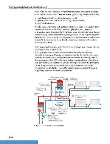
                                            Fully pumped systems with three or more two-port zone valves
                                            (known as the S-plan plus)
                                            The S-plan plus has three or more two-port motorised zone valves to
                                            control the primary and heating circuits separately by the cylinder and room
                                            thermostats respectively. This system is recommended for dwellings with a
                                            floor area greater than 150 m  because it allows the installation of additional
                                                                       2
                                            two-port zone valves to zone the upstairs heating circuit from the downstairs
                                            circuit. A separate room thermostat, and possibly a second time clock/
                                            programmer, would also be required for upstairs zoning. A system bypass is
                                            required for overheat protection of the boiler.


                                                             Upstairs timer switch  Upstairs room
                                                          System bypass           thermostat

                                                 Two-port zone                  Cylinder
                                                 valve to hot water             thermostat
                                             22 mm flow and
                                             return pipework        Two-port
                                                                   zone valve for
                                           Expansion               upstairs circuit
                                           vessel
                                                                                        Downstairs room
                                                                                        thermostat

                                                                    Two-port
                                                                  zone valve for
                                                                   downstairs
                                                                     circuit

                                                                      Wiring centre
                                                                      Programmer
                                                           Pressure gauge
                                                           Filling loop
                                                           Pressure relief valve
                                                           and discharge pipework

                                           p  Figure 7.18 The sealed S-plan plus system


                450


        9781510416482.indb   450                                                                                    29/03/19   9:02 PM
   457   458   459   460   461   462   463   464   465   466   467