
Page 76 - 2010-2022 hose manufactureing ability and guide
P. 76
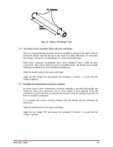
Fig. 6-2 – Nail or “Pot Room” Test


                     11.0    Procedure for hose assemblies fitted with metal end fittings:

                               When it is required that the resistance of a hose assembly be measured, the leads of the test
                          instrument shall  be attached  directly to the metal hose shank (threaded end connection,
                          fixed flange, stub end of a floating flange, etc.) of the metal end fittings.

                               Some  hoses,  especially  thermoplastic  hoses,  have  conductive  layers  within  the  hose
                          construction. These hoses shall be tested as assemblies made with fittings and assembly
                          techniques specified by the hose and fitting manufacturer.

                               Apply the metal contacts to the metal end fittings.

                               Apply the  test voltage (9V) and measure the resistance 5 seconds ± 1  second after the
                          voltage is applied.

                     12.0   Procedure for measurement of electrical continuity:

                               In certain types  of hose constructions, electrical continuity is provided between the  end
                          fittings by  means of  a  continuous wire  or wires bonded  to each coupling. When  the
                          construction is such that there are internal and external wires, the electrical continuity of
                          both wires shall be established.

                               It  is  essential  that contact  resistance between  the end fittings and the ohmmeter  be
                          minimized.

                               Apply the metal contacts to the metal end fittings.

                               Apply the  test voltage (9V) and measure the resistance 5 seconds ± 1  second after  the
                          voltage is applied.


                RMA/IP-2/2003                                                                             55