
Page 75 - 2010-2022 hose manufactureing ability and guide
P. 75
Dimensions in millimeters
Hose test piece, approx.
300
100
25 100 25
9 V d.c.
insulation tester Metallic foil
pieces wrapped
around conducting
electrodes and
held by clips
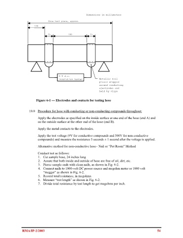
Figure 6-1 --- Electrodes and contacts for testing hose
10.0 Procedure for hose with conducting or non-conducting compounds throughout:
Apply the electrodes as specified on the inside surface at one end of the hose (end A) and
on the outside surface at the other end of the hose (end B).
Apply the metal contacts to the electrodes.
Apply the test voltage (9V for conductive compounds and 500V for non-conductive
compounds) and measure the resistance 5 seconds ± 1 second after the voltage is applied.
Alternative method for non-conductive hose– Nail or “Pot Room” Method
Conduct test as follows:
1. Cut sample hose, 24 inches long
2. Assure that both inside and outside of hose are free of oil, dirt, etc.
3. Pierce sample ends with clean nails, as shown in Fig. 6-2.
4. Connect nails to 1000-volt DC power source and megohm meter or 1000 volt
“megger” as shown in Fig. 6-2.
5. Record total resistance, in megohms.
6. Measure “test length” as shown in Fig. 6-2.
7. Divide total resistance by test length to get megohms per inch.
RMA/IP-2/2003 54