
Page 128 - REPOWER REFERENCE GUIDE (2020)
P. 128
Cooling System
Description Specification
Maximum pressure at the heater connections 172 kPa (25 psi)
IMPORTANT: The engine may not maintain proper temperature if the heater supply and return hoses are too large.
• The heater supply and return hose must not exceed 16 mm (5/8 in.) ID.
• Make heater connections only at the locations specified.
• Do not reposition the temperature senders or switches for the purpose of making the connections. Senders and switches
may not operate properly if repositioned.
• To avoid air locking, the heater should be mounted so that the heater element is below the connections on the engine. On
models with closed cooling, trapped air will eventually work its way back into the engine cooling system where it could
cause overheating.
• The system should be arranged so that the heater hoses slope progressively upward (toward the engine) to minimize the
need for air venting. Avoid U‑bends in the hoses.
• Hoses should be kept as short as possible with a minimum number of bends.
• Hoses should be properly supported to prevent chafing and interference with moving parts on the engine.
• Drain plugs should be fitted at the lowest point in the system for draining.
• On models with closed cooling, additional coolant must be added to the fresh water system to fill the heater. Operate the
engine while filling, and recheck the level several times to ensure that all air has been purged from the system.
IMPORTANT: If a heater is added, the coolant volume will be different than shown in the Operation, Maintenance, and
Warranty manual. Be sure to advise the owner of the proper coolant volume for the application.
• Refer to the heater manufacturer's instructions for specific installation details.
Propeller Shaft Log Seal Connections
NOTICE
Incorrectly installing the water supply hose to the shaft log seal can cause increased exhaust system corrosion, submersion,
or freeze damage due to siphoning. Position and securely fasten the water supply hose with a portion of the hose above the
engine exhaust elbows.
Route the propeller shaft log seal hose so that a portion of the hose extends above the top of the engine exhaust elbows to
prevent a siphoning action when the engine is not running. Securely fasten the hose to maintain its proper position.
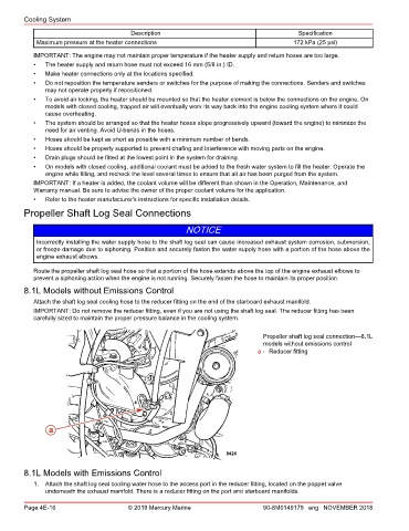
8.1L Models without Emissions Control
Attach the shaft log seal cooling hose to the reducer fitting on the end of the starboard exhaust manifold.
IMPORTANT: Do not remove the reducer fitting, even if you are not using the shaft log seal. The reducer fitting has been
carefully sized to maintain the proper pressure balance in the cooling system.
Propeller shaft log seal connection—8.1L
models without emissions control
a - Reducer fitting
a
8426
8.1L Models with Emissions Control
1. Attach the shaft log seal cooling water hose to the access port in the reducer fitting, located on the poppet valve
underneath the exhaust manifold. There is a reducer fitting on the port and starboard manifolds.
Page 4E-16 © 2019 Mercury Marine 90-8M0149179 eng NOVEMBER 2018