
Page 246 - REPOWER REFERENCE GUIDE (2020)
P. 246
8.1L/496 CID Engine
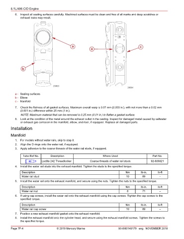
6. Inspect all sealing surfaces carefully. Machined surfaces must be clean and free of all marks and deep scratches or
exhaust leaks may result.
a c
a
b
20083
20084
a - Sealing surfaces
b - Elbow
c - Manifold
7. Check the flatness of all gasket surfaces. Maximum overall warp is 0.07 mm (0.003 in.), with not more than a 0.02 mm
(0.001 in.) difference within 25 mm (1 in.).
NOTE: Maximum material that can be removed is 0.25 mm (0.01 in.) to flatten a gasket surface.
8. Look at the condition of the metal around the exhaust outlet in the casting. Inspect for damaged metal caused by saltwater
or exhaust gas corrosion in the manifold, elbow, and riser, if equipped. Replace all damaged parts.
Installation
Manifold
1. For models without water rails, skip to step 8.
2. Align the O‑rings onto the water rail, if equipped.
3. Apply adhesive to the coarse threads of the water rail studs, if equipped.
Tube Ref No. Description Where Used Part No.
66 Loctite 242 Threadlocker Coarse threads of water rail studs 92-809821
4. Install the water rail studs into the exhaust manifold. Tighten the studs to the specified torque.
Description Nm lb‑in. lb‑ft
Water rail stud 10 89 –
5. Install the water rail onto the exhaust manifold, and secure using the nuts. Tighten the nuts to the specified torque.
Description Nm lb‑in. lb‑ft
Water rail nut 8 71 –
6. If using cap screws, install the water rail onto the exhaust manifold using the cap screws. Tighten the cap screws to the
specified torque.
Description Nm lb‑in. lb‑ft
Water rail cap screw 10 89 –
7. Position a new exhaust manifold gasket onto the exhaust manifold.
8. Install the exhaust manifold onto the cylinder head, and secure using the exhaust manifold screws. Tighten the screws to
the specified torque.
Page 7F-4 © 2019 Mercury Marine 90-8M0149179 eng NOVEMBER 2018