
Page 259 - REPOWER REFERENCE GUIDE (2020)
P. 259
8.1L/496/8.2L Triple Catalyst
10. Remove and discard the current gasket.
Cleaning and Inspection
IMPORTANT: Exhaust gaskets are not reusable.
1. Clean any gasket material from all surfaces.
2. Check the water passages for foreign material. The passages must be clean for efficient cooling.
3. Inspect all parts for damage or wear. Repair or replace as necessary.
4. To test the exhaust manifold, use block‑off plates, plugs, or short hoses with plugged ends. One block‑off plate must have
a threaded hole for attaching a compressed air hose. Use new gaskets when installing block‑off plates. Apply 138 kPa
(20 psi) of air pressure and submerge the manifold in water. Air bubbles indicate a leak.
5. Inspect all sealing surfaces carefully. Machined surfaces must be clean and free of all marks and deep scratches or
exhaust leaks may result.
6. Ensure that all mating surfaces are flat.
Description Maximum overall difference
Surface flatness 0.13 mm (0.005 in.) with not more than a 0.02 mm (0.0008 in.) difference within 25 mm (1 in.)
NOTE: The maximum material that can be removed is 0.25 mm (0.01 in.) to flatten a gasket surface.
7. Inspect the condition of the metal around the exhaust outlet in the casting. Inspect for damage caused by saltwater or
exhaust gas corrosion in the manifold, elbow, and riser, if equipped. Replace all damaged parts.
Exhaust Manifold Installation
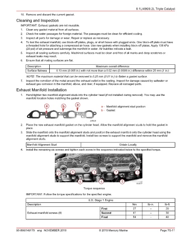
1. Hand‑tighten two manifold alignment studs into the cylinder head (if not installed during removal). You may use the
manifold location holes matching the gasket shown.
a b a a - Manifold alignment stud position
b - Gasket
49548
2. Place the new exhaust manifold gasket on the cylinder head. Allow the manifold alignment studs to hold the gasket in
place.
3. Slide the manifold onto the manifold alignment studs and position the exhaust manifold onto the cylinder head using the
manifold alignment studs to support the manifold. Install two screws to support the manifold and remove the manifold
alignment studs.
Manifold Alignment Stud Obtain Locally
4. Install the remaining six screws and tighten each screw in the sequence indicated below to the specified torque.
2 8 3 7 1
6 4 5
54477
Torque sequence
IMPORTANT: Follow the torque specifications for the specified engine.
8.2L Stage 1 Engine
Description Nm lb‑in. lb‑ft
First 27 – 20
Exhaust manifold screws (8) Second 41 – 30
Final 54 – 40
90-8M0149179 eng NOVEMBER 2018 © 2019 Mercury Marine Page 7G-11