
Page 23 - I:\Irrigation\Golf\
P. 23
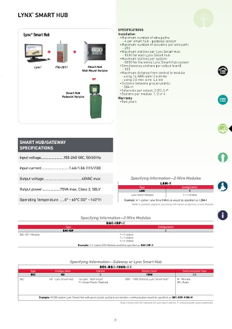
LYNX  SMART HUB
                 ®


                                                              SPECIFICATIONS
             Lynx® Smart Hub                                  Installation
                                                               • Maximum number of wire paths:
                                                                  - 4 per smart hub - pedestal version
                                                               • Maximum number of decoders per wire path:
                                                                  - 250
                                                               • Maximum stations per Lynx Smart Hub:
                                                                  - 1000 for each Lynx Smart Hub
                                                               • Maximum stations per system:
                                                                  - 5000 for the entire Lynx Smart Hub system
                   Lynx ®     FIU-2011        Smart Hub        • Simultaneous stations per output board:
                                           Wall Mount Version     - 100
                                                               • Maximum distance from central to module
                                                               - using 14 AWG wire: 2.6 miles
                                                or             - using 2,5 mm wire: 4,6 km
                                                               • Distance between ground points:
                                                               - 304 m
                                                               • Solenoids per output: 2 DCLS-P
                                   Smart Hub                   • Stations per module: 1, 2 or 4
                                 Pedestal Version             Warranty
                                                               • Two years


           SMART HUB/GATEWAY
           SPECIFICATIONS


           Input voltage .........................100-240 VAC, 50/60 Hz

           Input current ...............................1.6A/1.0A (115/230)

           Output voltage ..........................................40VAC max  Specifying Information—2-Wire Modules
                                                                                   LSM-1
           Output power ....................75VA max, Class 2, SELV      Type                 Configuration
                                                                         LSM                      1
                                                                    Lynx Smart Module          1—1-station

           Operating Temperature ......0° - 60°C (32° - 140°F)   Example: A 1-station Lynx Smart Module would be specified as: LSM-1
                                                                     *Refer to sprinkler pages for specifying information on Sprinkler 2-wire Modules


                                          Specifying Information—2-Wire Modules
                                                        DAC-ISP-X
                                   Type                                           Configuration
                                 DAC-ISP                                              X
           DAC-ISP—Module                                      1—1-station
                                                               2—2-station
                                                               4—4-station
                                         Example: A 2-station DAC Module would be specified as: DAC-ISP-2


                                     Specifying Information—Gateway or Lynx Smart Hub
                                                    DEC-RSX-1000-XX
                 Type        Configuration        Cabinet                 Station Count        Communication Type
                 DEC            RS                  X                       1000                    XX
           DEC            RS—Lynx Smart Hub  no code—Wall mount   1000—1000 Stations, Lynx Smart Hub*  M—Wireline
                                          P—Green Plastic Pedestal                          DR—Radio


                     Example: A1000 station Lynx Smart Hub with green plastic pedestal and wireline communication would be specified as: DEC-RSP-1000-M
                                                               Note: A blank after RS indicates the wall mount cabinet. P, indicates green plastic pedestals.


                                                            21