Page 15 - E BOOK ENGINE MECHANICAL M2
P. 15

2. MIVEC ENGINES


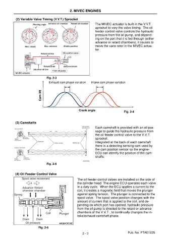
            (2) Variable Valve Timing (V.V.T.) Sprocket
                                                                   The MIVEC actuator is built-in the V.V.T.
                                                                   sprocket to vary the valve timing.  The oil
                                                                   feeder control valve controls the hydraulic
                                                                   pressure from the oil pump, and depend-
                                                                   ing on the port that it is fed through (either
                                                                   advance or retard chambers), it causes to
                                                                   move the vane rotor in the MIVEC actua-
                                                                   tor.


                                 Fig. 2-3
                                   Exhaust cam phase variation   Intake cam phase variation


                              Cam lift


                                                        Crank angle
                                                                                       Fig. 2-4


            (3) Camshafts
                                                                   Each camshaft is provided with an oil pas-
                                                                   sage to guide the hydraulic pressure from
                                                                   the oil feeder control valve to the V.V.T.
                                                                   sprocket.
                                                                   Integrated at the back of each camshaft
                                                                   there is a detecting sensing cam used by
                                                                   the cam position sensor so the engine-
                                                                   ECU can identify the position of the cam-
                                                                   shafts.

                                 Fig. 2-5


            (4) Oil Feeder Control Valve

                                                       The oil feeder control valves are installed on the side of
                                                       the cylinder head. The engine-ECU operates each valve
                                                       in a duty cycle.  When the ECU applies a current to the
                                                       coil, it creates a magnetic field that moves the plunger
                                                       against spring tension.  The plunger is connected to the
                                                       spool valve.  The spool valve position changes with the
                                                       amount of current that is applied to the coil, and de-
                                                       pending on which port has opened, hydraulic pressure
                                                       from the oil pump is directed to the retard or advance
                                                       chambers of the V.V.T., to continually changes the in-
                                                       take/exhaust camshaft phase.


                            Fig. 2-6

                                                          2 - 3                           Pub. No. PTAE1225
   10   11   12   13   14   15   16   17   18   19   20