Page 10 - E BOOK ENGINE MECHANICAL M2
P. 10

1. TECHNICAL FEATURES OF 4B1 ENGINE


                                      Auto tensioner    (9) Auxiliary Drive Belt
                                                        A  single  serpentine  belt  (one  piece)  drive  system  is
                                                        used to improve quietness. The  auto-tensioner is pro-
                                                        vided to make the belt tension adjustment as needed,
                                                        and to improve belt reliability.


                           Fig. 1-13


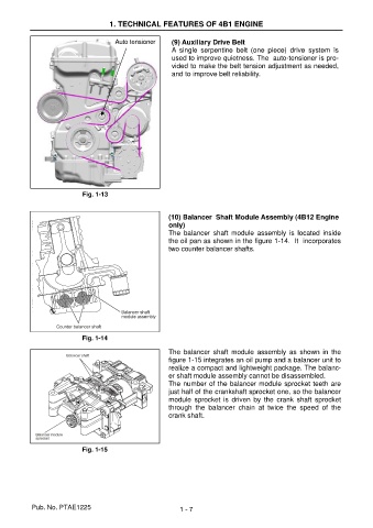
                                                       (10) Balancer  Shaft Module Assembly (4B12 Engine
                                                       only)
                                                       The  balancer  shaft  module  assembly  is  located  inside
                                                       the oil pan as shown in the figure 1-14.  It  incorporates
                                                       two counter balancer shafts.


                           Fig. 1-14

                                                       The  balancer  shaft  module  assembly  as  shown  in  the
                                                       figure 1-15 integrates an oil pump and a balancer unit to
                                                       realize a compact and lightweight package. The balanc-
                                                       er shaft module assembly cannot be disassembled.
                                                       The number of the balancer module sprocket teeth are
                                                       just half of the crankshaft sprocket one, so the balancer
                                                       module  sprocket  is  driven  by  the  crank  shaft  sprocket
                                                       through  the  balancer  chain  at  twice  the  speed  of  the
                                                       crank shaft.


                           Fig. 1-15


           Pub. No. PTAE1225                              1 - 7
   5   6   7   8   9   10   11   12   13   14   15