
Page 221 - The Effect of Hydrogen and Hydrides - ebook first test
P. 221
α
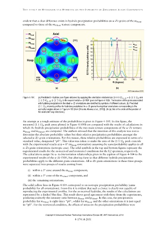
Figure 4-104: (a) Predicted hydride pole figure obtained by applying the orientation relationships {0 0 0 2} − ∥ (1 1 1) δ and
[1 1 2 ̅ 0] α−Zr ∥ (1 1 ̅ 0) to the experimental αZr ODF given in Figure 4-102b. The location of the poles associated
with hydride precipitation in the ideal αZr orientations are identified by symbols of different colours. (b) Predicted
(1 1 1) intensity profiles for hydrides precipitated in αZr grains having ideal orientations corresponding to the
azimuthal angles shown in Figure 4-100 (from [Vicente Alvarez et al., 2012]). (In (a) this is the circle at the junction of
the axial and hoop directions.)
(1 1 1)
α
α
(1 1 1)
= 0°
α
α-
α
α
Copyright © Advanced Nuclear Technology International Europe AB, ANT International, 2019.