
Page 68 - Unit2.docx
P. 68
© It's Engg. Life
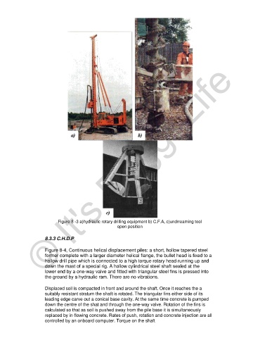
Figure 8 -3 a)hydraulic rotary drilling equipment b) C.F.A, c)undrreaming tool
open position
8.3.3 C.H.D.P
Figure 8-4, Continuous helical displacement piles: a short, hollow tapered steel
former complete with a larger diameter helical flange, the bullet head is fixed to a
hallow drill pipe which is connected to a high torque rotary head running up and
down the mast of a special rig. A hollow cylindrical steel shaft sealed at the
lower end by a one-way valve and fitted with triangular steel fins is pressed into
the ground by a hydraulic ram. There are no vibrations.
Displaced soil is compacted in front and around the shaft. Once it reaches the a
suitably resistant stratum the shaft is rotated. The triangular fins either side of its
leading edge carve out a conical base cavity. At the same time concrete is pumped
down the centre of the shat and through the one-way valve. Rotation of the fins is
calculated so that as soil is pushed away from the pile base it is simultaneously
replaced by in-flowing concrete. Rates of push, rotation and concrete injection are all
controlled by an onboard computer. Torque on the shaft