
Page 8 - Tension Structures
P. 8
8 Table 5: Capacity and Lengths of Architectural and Standard Compression Struts
Adjustable Compression Struts Maximum mm 2369 2663 2671 69.3 121.6 189.6 274.0 369.7 530.0 728.7 1063.9 1395.3 1588.6 2031.3
M85
M42
M30
M48
M16
M76
M56
M12
M20
M64
M100
M24
M90
M36
System Ref
compressive
14.0
44.7
kN
28.1
capacity to
EN1993
Maximum pin
to pin length
3105
6397
3367
7420
11679
7097
4498
8188
10291
3357
9323
on EN1993
standard*
Carbon
244.5
42.4
114.3
273
48.3
139.7
323.9
219.1
88.9
60.3
mm
33.7
193.7
168.3
76.1
CHS OD
Carbon CHS
5
6.3
5
5
16
16
mm
12.5
10
Wall
10
16
5
4
10
5
Thickness
Stainless
CHS OD
Stainless
Contact Macalloy for details
4.50
mm
5.08
4.85
CHS Wall mm 33.40 42.16 48.30 60.33 73.03 Contact Macalloy for details
5.08
5.16
thickness
*Maximum lengths are based on carbon steel strut taking the maximum compressive capacity. For lower compressive loads longer lengths can be used.
Alternative wall thicknesses are available. Contact Macalloy for details regarding maximum length of stainless steel struts.
Compression Strut Examples
Architectural Compression Strut
Standard Compression Strut
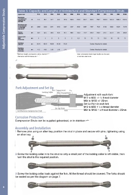
Fork Adjustment and Set Up
Min Engagement Pin
Locking Collar Max Engagement
Adjustment with each fork:
M12 to M56: +/- ½ thread diameter
M64 to M100: +/- 25mm
Set-Up Point in each fork
M12 to M56: 1 ½ x thread diameter
Set-Up Point
Architectural Compression Strut Fork M64 to M100: 1 x thread diameter + 25mm
Corrosion Protection
Compression Struts can be supplied galvanised, or in stainless steel.
Assembly and Installation
1 Remove pins using an allen key, position the strut in place and secure with pins, tightening using
an allen key.
2 Screw the locking collar in to the strut so only a small part of the locking collar is left visible, then
turn the strut to the required position.
3 Screw the locking collar back against the fork. All the thread should be covered. The forks should
be sealed as per the diagram on page 7.
8