
Page 9 - Tension Structures
P. 9
9
Table 5: Capacity and Lengths of Architectural and Standard Compression Struts Table 6: Capacity of Macalloy CHS Fork Ends
System Ref M12 M16 M20 M24 M30 M36 M42 M48 M56 M64 M76 M85 M90 M100 Macalloy Product Ref Units CSF CSF CSF CSF CSF CSF CSF CSF CSF CSF CSF CSF CSF CSF
42
36
48
64
56
16
12
90
30
24
20
76
85
100
Maximum
compressive kN 14.0 28.1 44.7 69.3 121.6 189.6 274.0 369.7 530.0 728.7 1063.9 1395.3 1588.6 2031.3 CHS Outer Diameter mm 33.7 42.4 48.3 60.3 76.1 88.9 114.3 139.7 168.3 193.7 219.1 244.5 273 323.9
capacity to Size
EN1993 to fit Wall thickness mm 4.0 5.0 5.0 5.0 5.0 5.0 6.3 10.0 10.0 10.0 12.5 16.0 16.0 16.0 Macalloy CHS Fork End
Maximum pin
to pin length mm 2369 2663 2671 3105 3357 3367 4498 6397 7097 7420 8188 9323 10291 11679 Compressive Capacity to EN 1993 kn 52 99 122 174 272 374 534 735 1048 1437 2127 2723 3110 3686
on EN1993
standard* Equivalent Macalloy Fork Size M12 M16 M20 M24 M30 M36 M42 M48 M56 M64 M76 M85 M90 M100
Carbon mm 33.7 42.4 48.3 60.3 76.1 88.9 114.3 139.7 168.3 193.7 219.1 244.5 273 323.9 Gusset Plate Thickness mm 10 12 15 20 22 30 35 40 45 55 70 70 80 85
CHS OD
Weight kg 0.25 0.51 1.0 1.4 2.4 3.7 6.2 10.8 15.8 20.5 40.3 59.3 74.0 100.0
Carbon CHS
Wall mm 4 5 5 5 5 5 6.3 10 10 10 12.5 16 16 16
Thickness
Macalloy CHS Fork End
Stainless mm 33.40 42.16 48.30 60.33 73.03 Contact Macalloy for details
CHS OD
Stainless
CHS Wall mm 4.50 4.85 5.08 5.08 5.16 Contact Macalloy for details
thickness
*Maximum lengths are based on carbon steel strut taking the maximum compressive capacity. For lower compressive loads longer lengths can be used.
Alternative wall thicknesses are available. Contact Macalloy for details regarding maximum length of stainless steel struts.
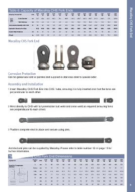
Corrosion Protection
Can be galvanised and or painted and supplied in stainless steel to special order.
Assembly and Installation
1 Insert Macalloy CHS Fork End into CHS / tube, ensuring it is fully inserted and that the forks are
perpendicular to each other.
2 Weld directly to CHS with full penetration butt weld and clean weld as required (ensuring forks
are perpendicular to each other)
3 Position complete strut in place and secure using pins.
Architectural pins can be supplied by Macalloy. Please refer to table number 12 on page 13 for
further information.
Table 7: Macalloy CHS Fork End Dimensions
System Ref Product Units CSF CSF CSF CSF CSF CSF CSF CSF CSF CSF CSF CSF CSF CSF
36
64
42
56
48
30
Ref.
16
12
85
76
100
24
20
90
A mm 75 95 109 130 161 185 218 255 303 340 398 462 495 574
Fixed End Compression
Strut fork
G (min.) mm 13 16 20 25 30 35 40 45 49.5 59.5 76 76 86 91
C Dia. mm 33.7 42.4 48.3 60.3 76.1 88.9 114.3 139.7 168.3 193.7 219.1 244.5 273 323.9
D Dia mm 13 17 21.5 25.5 31.5 37.5 43.5 49.5 57.5 65.5 78.5 91.5 96.5 111.5
E mm 22 29 34 42 52 61 70 81 97 111 132 153 162 189
Y mm 22 28 37 44 53 64 75 87 97.5 115.5 146 153 169 174
H mm 34 45 53 64 81 93 109 123 147 169 201 236 248 289 9