
Page 114 - Basic Course
P. 114
KNX BASIC COURSE
19 Checking the installation
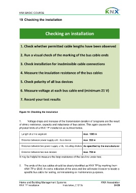
Checking an installation
1. Check whether permitted cable lengths have been observed
2. Run a visual check of the marking of the bus cable ends
3. Check installation for inadmissible cable connections
4. Measure the insulation resistance of the bus cables
5. Check polarity of all bus devices
6. Measure voltage at each bus cable end (minimum 21 V)
7. Record your test results
Figure 18: Checking the installation
1. Voltage drops and increase of the transmission duration of telegrams are the result
of ohmic resistance, capacity and inductance of bus cables. This again causes the
physical limits of a KNX TP installation as outlined below.
Length of a line segment max. 1000 m
Distance between power supply unit - bus device max. 350 m
Distance between two power supply units, including chokes As specified by the manufacturer
Distance between two bus devices max. 700 m
It may be helpful to measure the loop resistance of the bus line under test.
2. The ends of the bus cables should be clearly identified as KNX TP by marking them
KNX TP or BUS. An extra indication of the area and line will make it easier to locate a
specific bus cable for testing, commissioning or maintenance purposes.
Home and Building Management Systems KNX Association
KNX TP Installation Installation_E1213c 24/28