
Page 32 - Basic Course
P. 32
KNX BASIC COURSE
6 TP bit structure
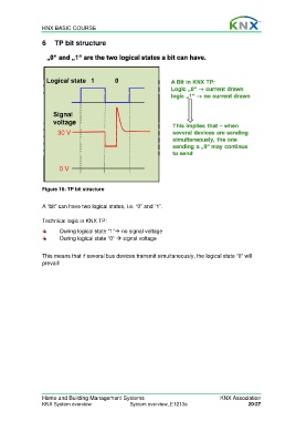
Figure 16: TP bit structure
A “bit” can have two logical states, i.e. “0” and “1”.
Technical logic in KNX TP:
During logical state “1” no signal voltage
During logical state “0” signal voltage
This means that if several bus devices transmit simultaneously, the logical state “0” will
prevail!
Home and Building Management Systems KNX Association
KNX System overview System overview_E1213a 20/27