
Page 6 - Advanced Course
P. 6
KNX ADVANCED COURSE
Figure 4: Priority of a telegram
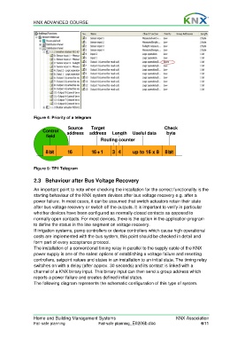
Source Target Check
Control address address Length Useful data byte
field
Routing counter
8bit 16 16+1 3 4 up to 16 x 8 8bit
Figure 5: TP1 Telegram
2.3 Behaviour after Bus Voltage Recovery
An important point to note when checking the installation for the correct functionality is the
starting behaviour of the KNX system devices after bus voltage recovery e.g. after a
power failure. In most cases, it can be assumed that switch actuators retain their state
after bus voltage recovery or switch off the outputs. It is important to verify in particular
whether devices have been configured as normally closed contacts as opposed to
normally open contacts. For most devices, there is the option in the application program
to define the status in the line segment on voltage recovery.
If irrigation systems, pump controllers or device controllers which cause high operational
costs are implemented with the bus system, this point should be checked in detail and
form part of every acceptance protocol.
The installation of a conventional timing relay in parallel to the supply cable of the KNX
power supply is one of the safest options of establishing a voltage failure and resetting
controllers, setpoint values and states in an installation to an initial state. The timing relay
switches on with a delay (after approx. 30 seconds) and its contact is linked with a
channel of a KNX binary input. This binary input can then send a group address which
reports a power failure and creates defined initial states.
The following diagram represents the schematic configuration of this type of system.
Home and Building Management Systems KNX Association
Fail-safe planning Fail-safe planning_E0206b.doc 6/11