
Page 9 - Advanced Course
P. 9
KNX ADVANCED COURSE
3.2 Logic Modules and Visualisation in Connection with Couplers
In KNX systems that extend over several rooms, it is advisable to distribute the controllers
i.e. to position several modules. The fault tolerance is thereby increased. It also relieves
the load from the filter tables and the telegram traffic across the lines and areas is
reduced to a minimum.
If a visualisation program is present in a KNX system, it can take over logic functions and
sequence control in many cases. Products are also available on the market which support
basic programming languages which are similar to C or Pascal. It is of course also
possible to use the visualisation as a large controller. This is however not a good idea as
regards operational reliability, since a failure of the PC will lead to the functions in the
KNX system no longer being guaranteed. It is advisable in any case to connect the PC on
which the visualisation is installed to a UPS. In general however a control option should
always be provided next to the PC to ensure emergency operation. This can take the form
of a switch sensor or panel units for example.
3.3 Multi-channel Switch Actuators
When costing KNX systems, multi-channel switch actuators are being installed with
increasing frequency. These devices appear perhaps to be a good idea in most cases as
regards project costs but a possible disruption of the device means that several loads can
no longer be controlled in the event of a fault. This fact should also be considered when
planning a KNX system. If output devices are used however with many channels, it may
be advisable to select the assignment so that complete areas of the building are not
affected by the malfunction if a device fails (see the example).
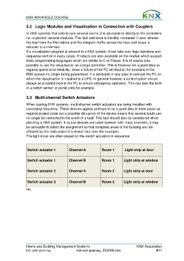
The light strips are often placed on the switch actuators in sequence:
Switch actuator 1 Channel A Room 1 Light strip at door
Switch actuator 1 Channel B Room 1 Light strip at window
Switch actuator 2 Channel A Room 2 Light strip at door
Switch actuator 2 Channel B Room 2 Light strip at window
etc.
Home and Building Management Systems KNX Association
Fail-safe planning Fail-safe planning_E0206b.doc 9/11