Page 143 - Digital Electronics by harish
P. 143

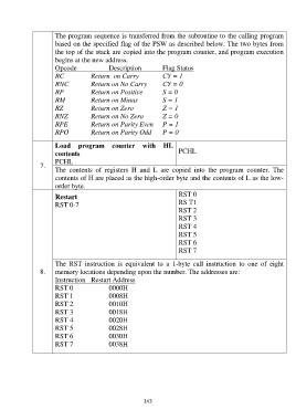
The program sequence is transferred from the subroutine to the calling program
                       based on the specified flag of the PSW as described below. The two bytes from
                       the top of the stack are copied into the program counter, and program execution
                       begins at the new address.
                       Opcode                Description          Flag Status
                       RC             Return  on Carry            CY = 1
                       RNC            Return on No Carry          CY = 0
                       RP             Return on Positive          S = 0
                       RM             Return on Minus             S = 1
                       RZ             Return on Zero              Z = 1
                       RNZ            Return on No Zero           Z = 0
                       RPE            Return on Parity Even       P = 1
                       RPO            Return on Parity Odd        P = 0


                       Load  program  counter  with  HL
                       contents                                          PCHL
                       PCHL
                 7.
                       The  contents  of  registers  H  and  L  are  copied  into  the  program  counter.  The
                       contents of H are placed as the high-order byte and the contents of L as the low-
                       order byte.
                       Restart                                           RST 0
                       RST 0-7                                           RS T1
                                                                         RST 2
                                                                         RST 3
                                                                         RST 4
                                                                         RST 5
                                                                         RST 6
                                                                         RST 7

                       The  RST  instruction  is  equivalent  to  a  1-byte  call  instruction  to  one  of  eight
                 8.    memory locations depending upon the number. The addresses are:
                       Instruction  Restart Address
                       RST 0                 0000H
                       RST 1                 0008H
                       RST 2                 0010H
                       RST 3                 0018H
                       RST 4                 0020H
                       RST 5                 0028H
                       RST 6                 0030H
                       RST 7                 0038H


                                                           143
   138   139   140   141   142   143   144   145   146   147   148