
Page 43 - Digital Electronics by harish
P. 43
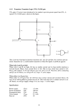
1.5.3  Transistor-Transistor Logic (TTL) NAND gate

               TTL gates (74 series) were introduced in the market to provide greater speed than DTL. A
               typical TTL NAND gate is shown in the figure.


               This circuit has four bipolar junction transistors (Q1, Q2, Q3 and Q4), four resistors and one
               diode. Transistor Q1 is a multi-emitter transistor in which the inputs A and B are applied.

               When both A and B are high:
               When  both  A  and  B  are  high,  Q1  has  no  emitter  current  and  its  base-emitter  junction  is
               forward  biased.  Hence,  base  current  flows  to  Q2.  This  in  turn,  feeds  base  current  to  Q4.
               Hence, Q4 conducts. As the Q2 collector goes low, Q3 is cut-off. Therefore, Q4 is conducting
               and Q3 cut-off. Hence, we will get 0V (ie.) logic „0‟ at the output.

               When either A or B goes low:
               When either A or B goes low, Q1 will have base-emitter current and saturated. Hence, the
               base of Q2 will be pulled to ground and cut-off. This will cause Q3 to conduct and Q4 to cut-
               off. Hence, we will get supply voltage (Vcc) (ie.) logic „1‟ at the output.

               Specifications:

               Power supply          (Vcc)         +5 volts
               Power dissipation     (Pd)          100 mw
               Propagation delay     (Td)          15 nsec
               Noise margin          (V NM)        0.4 volts
               Fan-out               (FO)          10


                                                           43