
Page 45 - Digital Electronics by harish
P. 45
Comparison of TTL and CMOS logic families
Sl. No. Parameter TTL CMOS
1. Power Supply voltage 5 volts 3 to 15 volts
2. Power dissipation 100 mW (milli watt) 10 nW (nano watt)
3. Propagation delay 15 nsec (nano seconds) 25 nsec (nano seconds)
4. Noise margin 0.4 volts 45% of V DD
5. Fan-out 10 Greater than 50
Applications of TTL and CMOS logic gates
TTL and CMOS logic gates are used in digital circuits, memories, etc. CMOS gates
are preferred over TTL for lower power applications such as battery operated devices.
1.5.5 Tristate Logic (TSL) gate
We know only two logic states namely low level „0‟ and high level „1‟. But there is a third
logic state which is called „high impedance‟ state. In this third state, even though the output is
physically connected in the circuit, it behaves like an open circuit. A gate with high
impedance state is called Tristate gate.
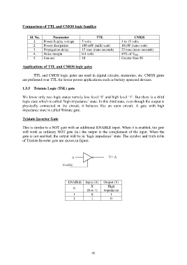
Tristate Inverter Gate
This is similar to a NOT gate with an additional ENABLE input. When it is enabled, the gate
will work as ordinary NOT gate (ie.) the output is the complement of the input. When the
gate is not enabled, the output will be in „high impedance‟ state. The symbol and truth table
of Tristate Inverter gate are shown in figure.
ENABLE Input (A) Output (Y)
X High
0
(0 or 1) impedance
1 0 1
1 1 0
45