Page 62 - Digital Electronics by harish
P. 62

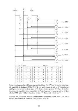
Control Input                          Output
                           C     B      A     Y 7    Y 6   Y 5    Y 4    Y 3   Y 2    Y 1   Y 0
                           0      0     0      0     0      0      0     0      0     0      1
                           0      0     1      0     0      0      0     0      0     1      0
                           0      1     0      0     0      0      0     0      1     0      0
                           0      1     1      0     0      0      0     1      0     0      0
                           1      0     0      0     0      0      1     0      0     0      0
                           1      0     1      0     0      1      0     0      0     0      0
                           1      1     0      0     1      0      0     0      0     0      0
                           1      1     1      1     0      0      0     0      0     0      0

               In the logic diagram, the AND gates are numbered from 0 to 9. When the control input lines
                                                    th
               CBA are 000, all the inputs  of 0  AND gate are 1. Hence, Y 0 will be „1‟. But all other
               AND gates will have at least one input as „0‟. Hence, their outputs are „0‟. When the control
                                                              st
               input lines CBA are 001, all the inputs A of 1  AND gate are 1. Hence, Y 1 will be „1‟. But
               all other AND gates will have atleast one input as „0‟. Hence, their outputs are „0‟.

               Similarly,  the  outputs  for  all  other  control  input  combinations  can  be  found.  The  3-to-8
               decoder is available in IC form also. The IC number is 74138.


                                                           62
   57   58   59   60   61   62   63   64   65   66   67